Panel Modules
The control panel supports a number of different modules
installed into blank slots on the control panel or a
SideBox or SideBoxNet connected to the switcher.
For information on installing a module into the control
panel, SideBox, or SideBoxNet, refer to the
documentation that came with your module.
Installing or Replacing a Module
To install a module, you must rst remove the existing
module, or blank cover plate, that is installed in the
module opening. After the module has been removed,
you must install and cable the new module into the empty
module opening.
To Remove a Module
1. Lift up the control panel lid and turn off all power
supplies in the control panel.
2. Disconnect the power supplies from mains power.
3. Identify the module or blank cover plate that you
want to remove.
4. If you are removing a module, you must disconnect
the cables to the module.
Figure 13: Module Cables
a) Disconnect the 4-conductor Module Power
Cable from the module.
This cable delivers power to all of the modules
in the row. When unplugging the cable, ensure
that you do not accidentally unplug it from any
neighbouring modules.
b) Disconnect both the CAT5 Module Control
Link Cables from the module.
This cable delivers all of the command signal
to and from the module, as well as other
modules in the same row.
5. Use a 1/4 inch hex driver to remove the four
Retaining Nuts located at each corner of the module.
Front of Control Panel
Retaining Nuts
Figure 14: Remove Module Cover Plate
6. Remove the module or blank cover plate from the
control panel.
To Install a Module
1. Lift up the control panel lid and turn off all power
supplies in the control panel.
2. Disconnect the power supplies from mains power.
3. Install the module into the control panel.
4. Use a 1/4 inch hex driver to install the four Retaining
Nuts located at each corner of the module.
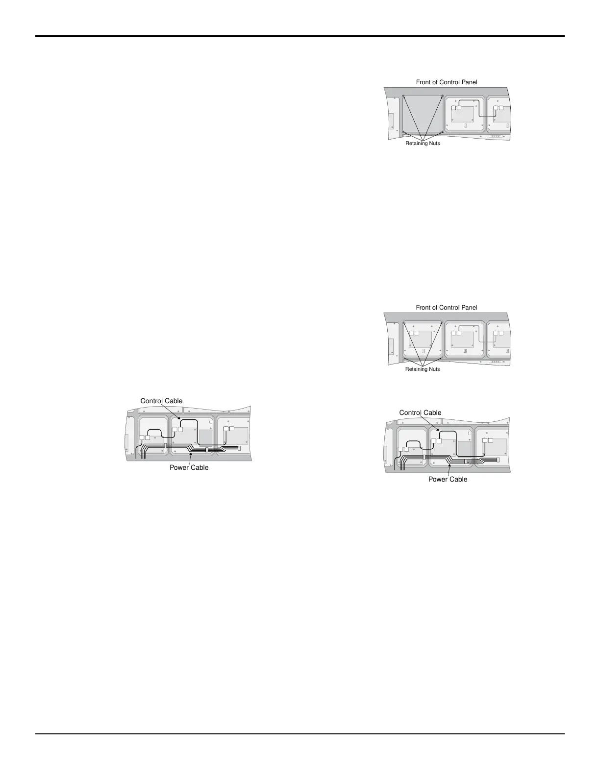
Front of Control Panel
Retaining Nuts
Figure 15: Install Module
5. Connect the cables to the module.
Figure 16: Module Cables
a) Connect the 4-conductor Module Power Cable
to the module.
This cable delivers power to all of the modules
in the row. When connecting the cable, ensure
that you do not accidentally unplug it from any
neighbouring modules.
b) Connect both of the CAT5 Module Control Link
Cables to the module.
This cable delivers all of the command signals
to and from the module, as well as other
modules in the same row.
To Upgrade a PMC
The Panel Module Controllers (PMCs) may need to be
upgraded if you perform a software upgrade or replace
a module. If PMCs need to be upgraded, the message
PMCs need to be upgraded; please go
Acuity Setup Manual (v9.2) — Panel Modules • 73
 Loading...


