-22-
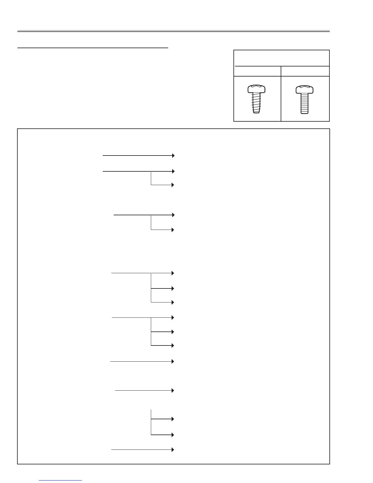
Mechanical disassembly flow chart
Mechanical disassembly should be made by following procedures chart.
Following steps show the basic procedures, therefore unnecessary step may
be ignored.
Caution:
The parts and screws should be placed exactly the same position as the origi-
nal otherwise it may cause loss of performance and product safety.
The wiring method of the leads and ferrite cores should be returned exactly the
same state as the original, otherwise it may cause lose of performance and
product safety.
Screws Expression
(Type Diameter x Length) mm
T type M Type
Mechanical Disassembly
1 Cabinet front cover removal
2 Cabinet front removal 2-1 LED and RC front board removal
3 Cabinet top removal
3-1 Lamp cover removal
3-2 Filter cover removal
4 Main board removal
5 Filter holder assy removal 5-1 Filter holder disassembly
5-2 Filter motor assy disassembly
6 Shutter assy, motor, lens-net and RC rear bards removal
7 Ex sensor, RGB fan-net, lamp fan-net, Illumi boards removal
8 Side panel assy removal 8-1 Side panel assy disassembly-1
8-2 Side panel assy disassembly-2
8-3 AV assy disassembly
9 Power box assy removal 9-1 Power box assy removal-1
9-2 Power box assy disassembly-1
9-3 Power box assy disassembly-2
10 Lens shift assy removal 10-1 Lens shift assy disassembly
11 Optical unit removal
12 Optical lamp unit removal 12-1 Lamp ID IF board and Fans removal
13 Lens cover holder and AC inlet assy removal
13-1 AC inlet assy disassembly
13-2 Wiring of the AC inlet assy
14 Duct cover assy removal 14-1 Duct cover assy disassembly
 Loading...


