-36-
Mechanical Disassembly
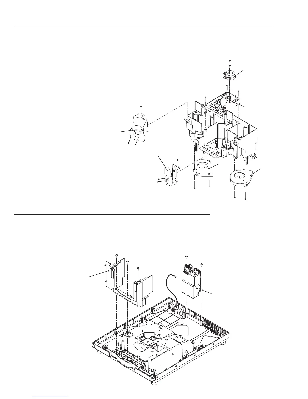
12-1 Lamp ID IF board and Fans removal
1 Remove fans on the bottom of the optical lamp unit.
FN908 with 2 screws-B(T3x40), FN909 with 2 screws-C(T3x40)
2 Remove fans on the top and side of the optical lamp unit.
Remove 4 screws-D(M3x30) and remove the optical lamp unit top.
Remove 1 screw-E(T3x8) and remove 2 screws-F(M4x25) and remove FN911.
Remove 1 screw-G(T3x8) and remove 2 screws-H(M4x25) and remove FN910.
Remove 2 screws-J(T3x12) and remove FN912.
C
F
B
H
J
E
G
FN912
FN908
FN909
FN911
FN910
13 Lens cover holder and AC inlet assy removal
1 Remove 3 screws-A(T4x10) and remove the lens cover holder upward off.
2 Remove 2 screws-B(T4x10) and remove the AC inlet assy upward off.
A
A
A
B
B
AC inlet assy
Lens cover holder
C
B
D
D
D
D
Optical lamp
unit top
 Loading...


