-29-
Mechanical Disassembly
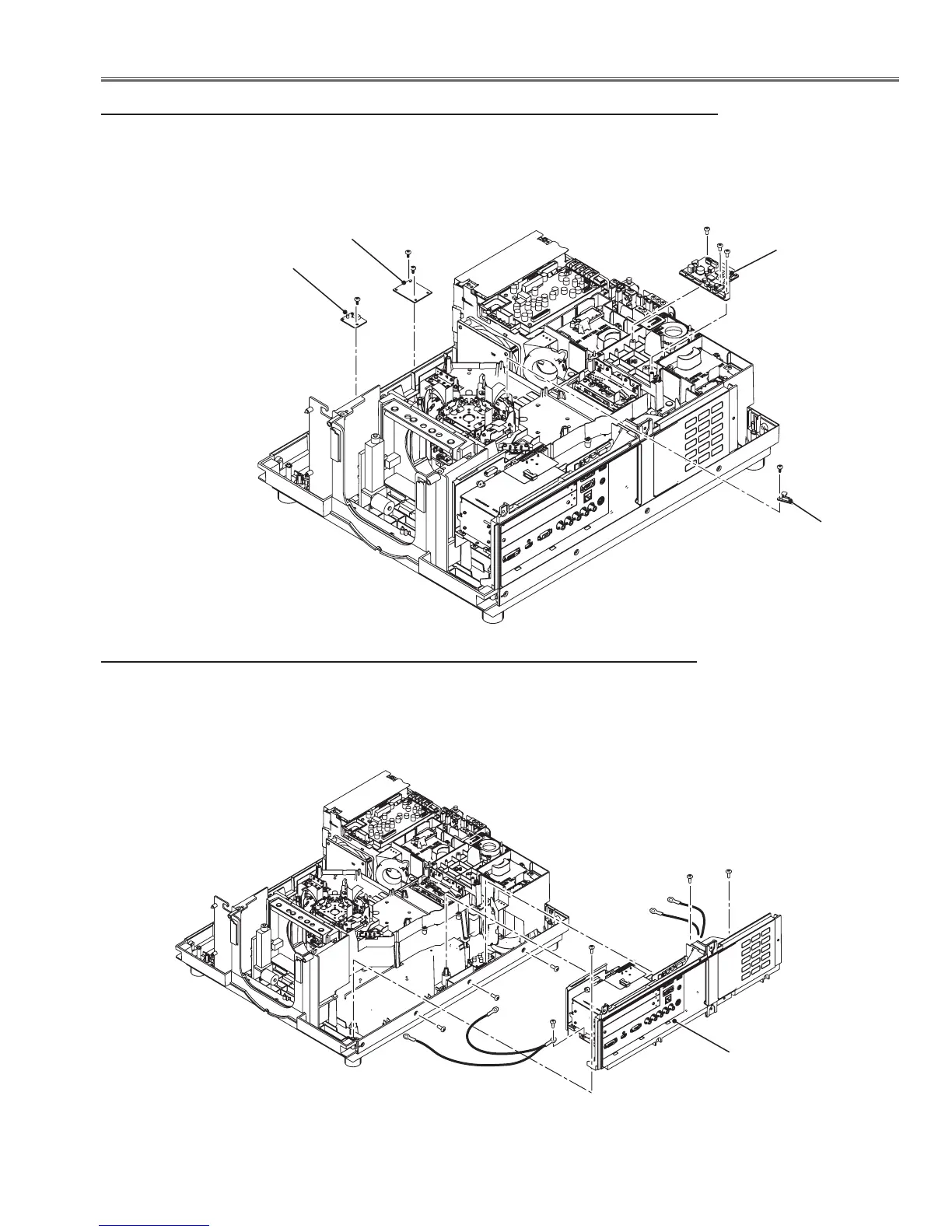
7 Ex temp, RGB fan-net, Lamp fan-net , Illumi sensor boards removal
1 Remove 1 screw-A (T3x8) and remove the sensor board.
2 Remove 2 screws-B (T3x8) and remove the RGB fan-net board.
3 Remove 3 screws-C (T3x8) and remove the lamp fan-net board.
4 Remove 1 screw-D (T3x8) and remove the Illumi sensor board.
A
B
B
C
C
Lamp fan-net board
RGB fan-net board
Ex temp board
8 Side panel assy removal
1 Remove 3 screws-A (M4x10) and 3 screws-B (T4x10) and remove the side panel
assy upward off.
A
A
A
B
B
B
Side panel assy
To: FG Net
board
D
Illumi sensor
board
C
 Loading...


