-35-
Mechanical Disassembly
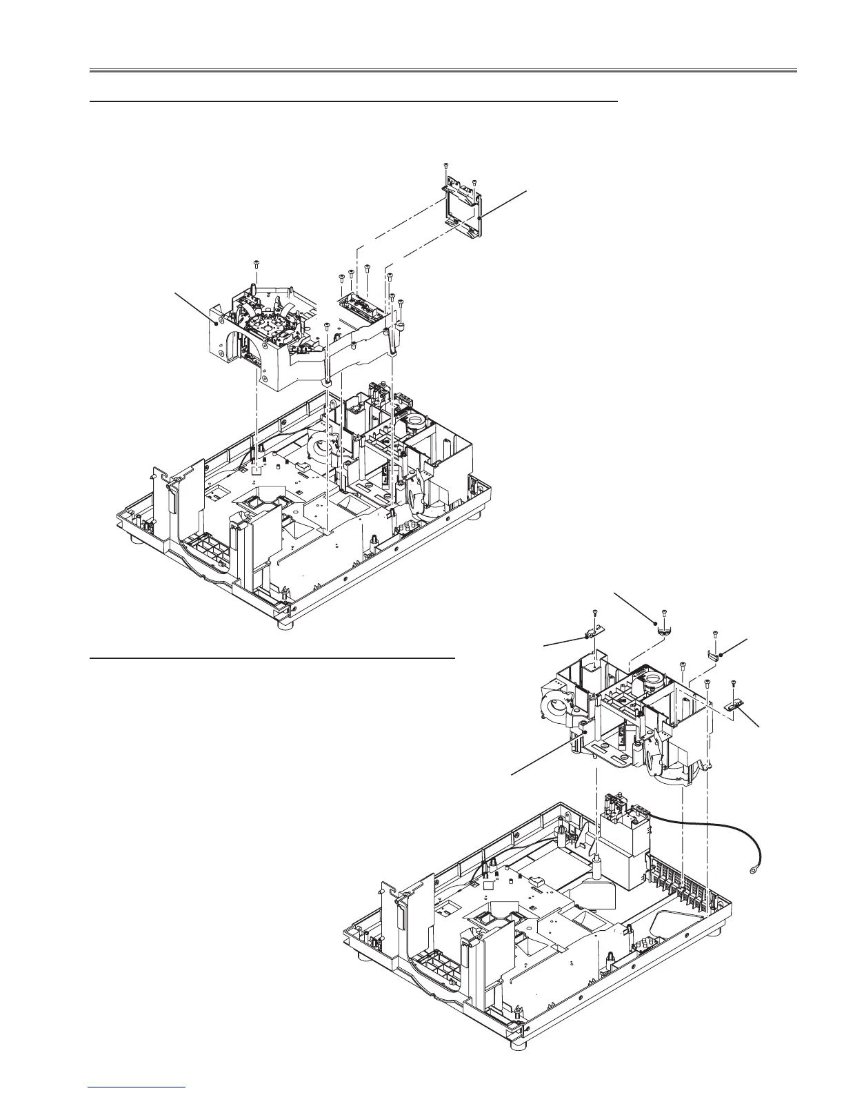
11 Optical unit removal
1 Remove 2 screws-A(M3x6) and remove the integrator-in assy upward off.
2 Remove 4 screws-B(M4x12) and 4 screws-C(T4x10) and remove the optical unit assy
upward off.
A
A
B
B
C
C
C
C
12 Optical lamp unit removal
1 Remove 2 screws-A(T4x10) and remove the optical lamp
unit assy upward off.
2 Remove each 1 screw-B(M3x10) and remove the thermal
switches (SW903 and SW904).
3 Remove each 1 screw-C(T3x8) and remove the Lamp ID
IF boards.
A
A
B
B
Integrator-in assy
Optical unit assy
Optical lamp unit assy
SW904
SW903
B
B
To:
FG Net
board
C
C
Lamp ID2 IF
board
Lamp ID1 IF
board
 Loading...


