-58-
Optical Adjustment
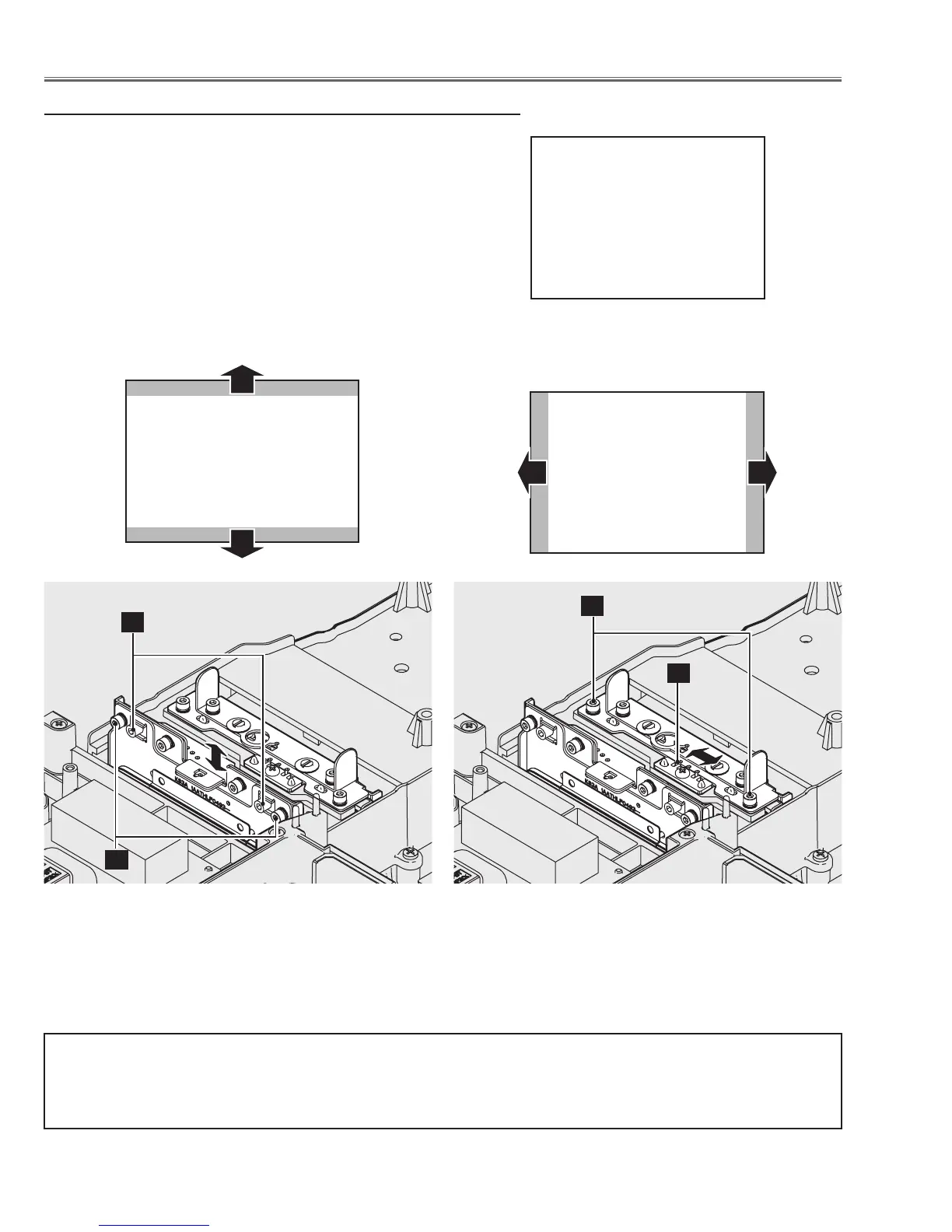
v Integrator adjustment-2
1 Move the Integrator-out and Integrator-in to remove the color bands
on the top/bottom or left/right of the screen.
1) To adjust the image vertically as shown in Fig.4-1, loosen 2
screws A, and turn the screws B by using hex drivers.
2) To adjust the image horizontally as shown in Fig.4-2, loosen 2
screws C, and move the slot D by using a slot screwdriver.
2 Tighten screws A and C to fix the Integrator-out and Integrator-in
unit.
(Target screen image)
Fig.4-1 Fig.4-2
After completing the optical center adjustment, replace the optical adjustment tools with the polarized
glass/optical filter assy and connect the LCD panel cables and connectors on the main board.
 Loading...


