Date Code 20001006 Overcurrent, Voltage, Synchronism Check, Frequency, and Power Elements 3-25
SEL-351 Instruction Manual
Settings Ranges
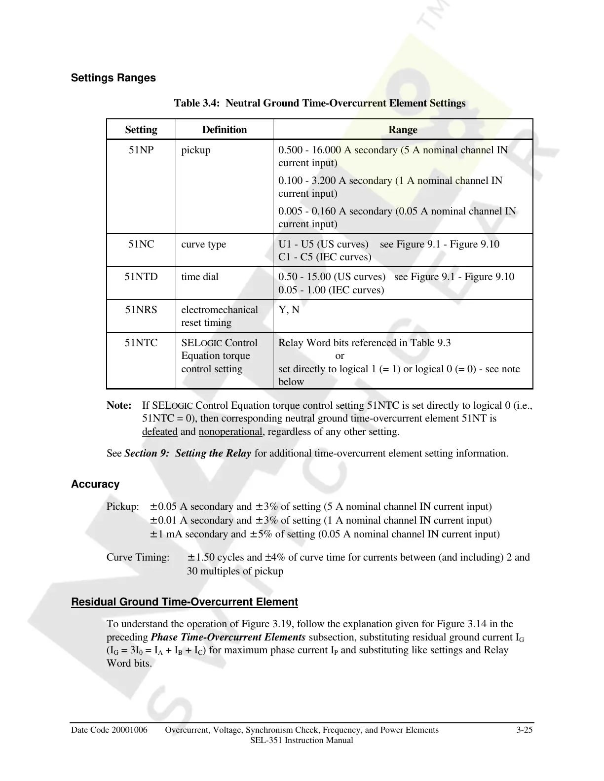
Table 3.4: Neutral Ground Time-Overcurrent Element Settings
Setting Definition Range
51NP pickup 0.500 - 16.000 A secondary (5 A nominal channel IN
current input)
0.100 - 3.200 A secondary (1 A nominal channel IN
current input)
0.005 - 0.160 A secondary (0.05 A nominal channel IN
current input)
51NC curve type U1 - U5 (US curves) see Figure 9.1 - Figure 9.10
C1 - C5 (IEC curves)
51NTD time dial 0.50 - 15.00 (US curves) see Figure 9.1 - Figure 9.10
0.05 - 1.00 (IEC curves)
51NRS electromechanical
reset timing
Y, N
51NTC SELOGIC Control
Equation torque
control setting
Relay Word bits referenced in Table 9.3
or
set directly to logical 1 (= 1) or logical 0 (= 0) - see note
below
Note: If SELOGIC Control Equation torque control setting 51NTC is set directly to logical 0 (i.e.,
51NTC = 0), then corresponding neutral ground time-overcurrent element 51NT is
defeated and nonoperational, regardless of any other setting.
See Section 9: Setting the Relay for additional time-overcurrent element setting information.
Accuracy
Pickup: ±0.05 A secondary and ±3% of setting (5 A nominal channel IN current input)
±0.01 A secondary and ±3% of setting (1 A nominal channel IN current input)
±1 mA secondary and ±5% of setting (0.05 A nominal channel IN current input)
Curve Timing: ±1.50 cycles and ±4% of curve time for currents between (and including) 2 and
30 multiples of pickup
Residual Ground Time-Overcurrent Element
To understand the operation of Figure 3.19, follow the explanation given for Figure 3.14 in the
preceding Phase Time-Overcurrent Elements subsection, substituting residual ground current I
G
(I
G
= 3I
0
= I
A
+ I
B
+ I
C
) for maximum phase current I
P
and substituting like settings and Relay
Word bits.
Courtesy of NationalSwitchgear.com