5-18 Trip and Target Logic Date Code 20001006
SEL-351 Instruction Manual
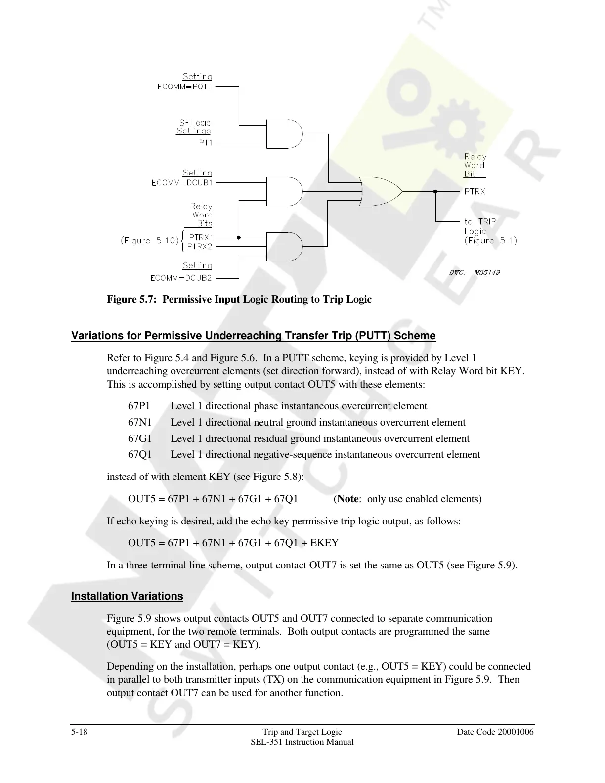
Figure 5.7: Permissive Input Logic Routing to Trip Logic
Variations for Permissive Underreaching Transfer Trip (PUTT) Scheme
Refer to Figure 5.4 and Figure 5.6. In a PUTT scheme, keying is provided by Level 1
underreaching overcurrent elements (set direction forward), instead of with Relay Word bit KEY.
This is accomplished by setting output contact OUT5 with these elements:
67P1 Level 1 directional phase instantaneous overcurrent element
67N1 Level 1 directional neutral ground instantaneous overcurrent element
67G1 Level 1 directional residual ground instantaneous overcurrent element
67Q1 Level 1 directional negative-sequence instantaneous overcurrent element
instead of with element KEY (see Figure 5.8):
OUT5 = 67P1 + 67N1 + 67G1 + 67Q1 (Note: only use enabled elements)
If echo keying is desired, add the echo key permissive trip logic output, as follows:
OUT5 = 67P1 + 67N1 + 67G1 + 67Q1 + EKEY
In a three-terminal line scheme, output contact OUT7 is set the same as OUT5 (see Figure 5.9).
Installation Variations
Figure 5.9 shows output contacts OUT5 and OUT7 connected to separate communication
equipment, for the two remote terminals. Both output contacts are programmed the same
(OUT5 = KEY and OUT7 = KEY).
Depending on the installation, perhaps one output contact (e.g., OUT5 = KEY) could be connected
in parallel to both transmitter inputs (TX) on the communication equipment in Figure 5.9. Then
output contact OUT7 can be used for another function.
Courtesy of NationalSwitchgear.com

 Loading...


