Date Code 20001006 Overcurrent, Voltage, Synchronism Check, Frequency, and Power Elements 3-29
SEL-351 Instruction Manual
VOLTAGE ELEMENTS
Enable numerous voltage elements by making the enable setting:
EVOLT = Y
Voltage Values
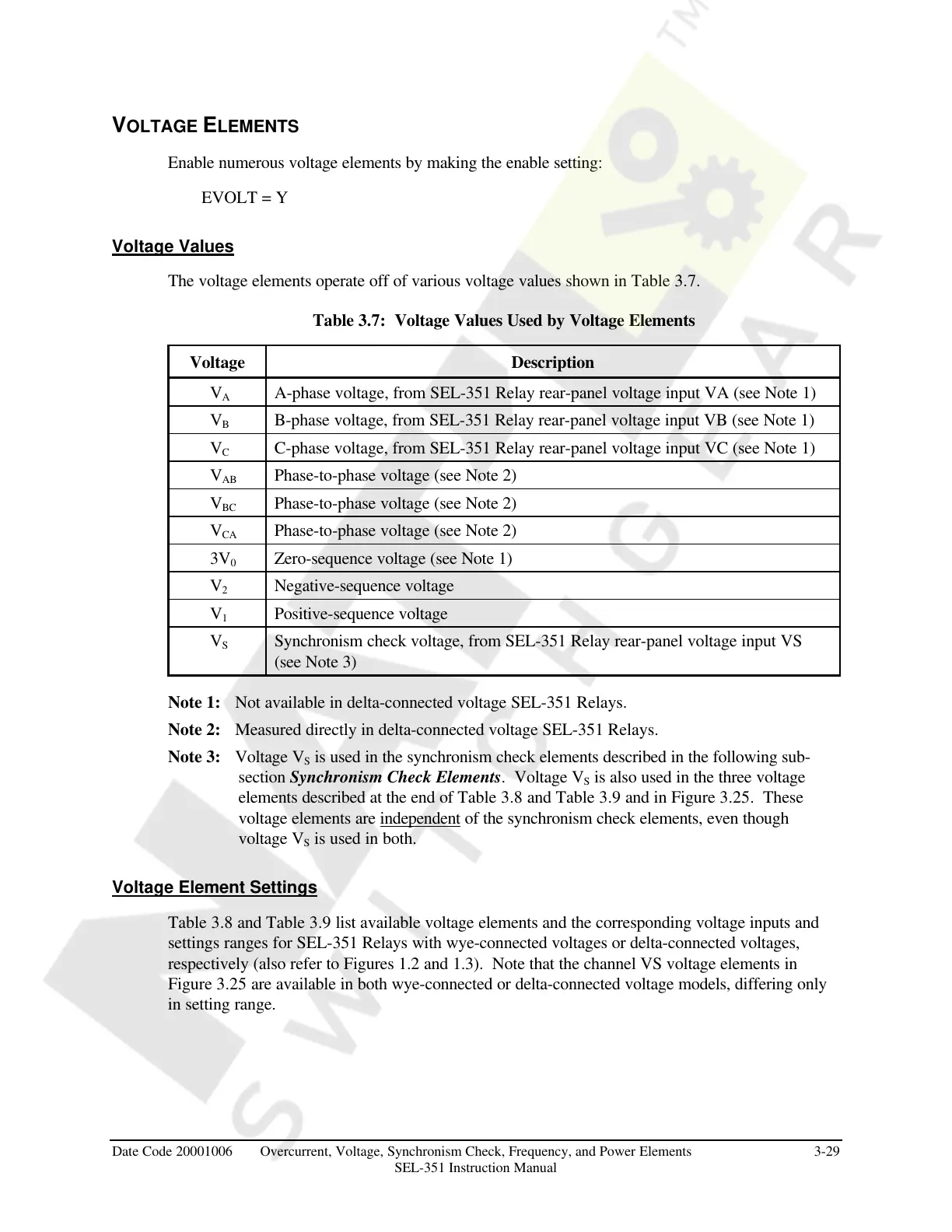
The voltage elements operate off of various voltage values shown in Table 3.7.
Table 3.7: Voltage Values Used by Voltage Elements
Voltage Description
V
A
A-phase voltage, from SEL-351 Relay rear-panel voltage input VA (see Note 1)
V
B
B-phase voltage, from SEL-351 Relay rear-panel voltage input VB (see Note 1)
V
C
C-phase voltage, from SEL-351 Relay rear-panel voltage input VC (see Note 1)
V
AB
Phase-to-phase voltage (see Note 2)
V
BC
Phase-to-phase voltage (see Note 2)
V
CA
Phase-to-phase voltage (see Note 2)
3V
0
Zero-sequence voltage (see Note 1)
V
2
Negative-sequence voltage
V
1
Positive-sequence voltage
V
S
Synchronism check voltage, from SEL-351 Relay rear-panel voltage input VS
(see Note 3)
Note 1: Not available in delta-connected voltage SEL-351 Relays.
Note 2: Measured directly in delta-connected voltage SEL-351 Relays.
Note 3: Voltage V
S
is used in the synchronism check elements described in the following sub-
section Synchronism Check Elements. Voltage V
S
is also used in the three voltage
elements described at the end of Table 3.8 and Table 3.9 and in Figure 3.25. These
voltage elements are independent of the synchronism check elements, even though
voltage V
S
is used in both.
Voltage Element Settings
Table 3.8 and Table 3.9 list available voltage elements and the corresponding voltage inputs and
settings ranges for SEL-351 Relays with wye-connected voltages or delta-connected voltages,
respectively (also refer to Figures 1.2 and 1.3). Note that the channel VS voltage elements in
Figure 3.25 are available in both wye-connected or delta-connected voltage models, differing only
in setting range.
Courtesy of NationalSwitchgear.com



 To Next Page