Date Code 20001006 Standard Event Reports, Sag/Swell/Interruption Report, and SER
SEL-351 Instruction Manual
12-23
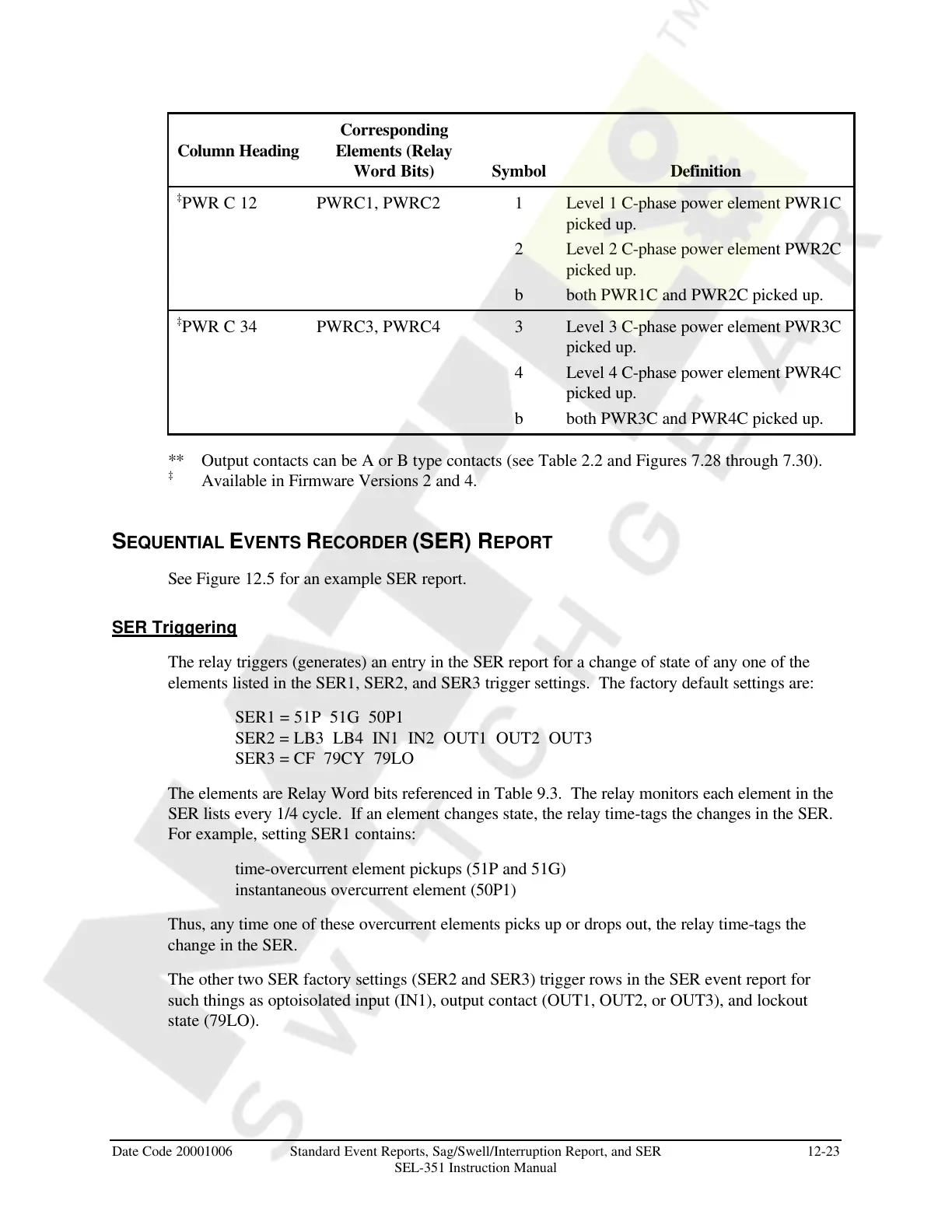
Column Heading
Corresponding
Elements (Relay
Word Bits) Symbol Definition
‡
PWR C 12 PWRC1, PWRC2 1 Level 1 C-phase power element PWR1C
picked up.
2 Level 2 C-phase power element PWR2C
picked up.
b both PWR1C and PWR2C picked up.
‡
PWR C 34 PWRC3, PWRC4 3 Level 3 C-phase power element PWR3C
picked up.
4 Level 4 C-phase power element PWR4C
picked up.
b both PWR3C and PWR4C picked up.
** Output contacts can be A or B type contacts (see Table 2.2 and Figures 7.28 through 7.30).
‡
Available in Firmware Versions 2 and 4.
SEQUENTIAL EVENTS RECORDER (SER) REPORT
See Figure 12.5 for an example SER report.
SER Triggering
The relay triggers (generates) an entry in the SER report for a change of state of any one of the
elements listed in the SER1, SER2, and SER3 trigger settings. The factory default settings are:
SER1 = 51P 51G 50P1
SER2 = LB3 LB4 IN1 IN2 OUT1 OUT2 OUT3
SER3 = CF 79CY 79LO
The elements are Relay Word bits referenced in Table 9.3. The relay monitors each element in the
SER lists every 1/4 cycle. If an element changes state, the relay time-tags the changes in the SER.
For example, setting SER1 contains:
time-overcurrent element pickups (51P and 51G)
instantaneous overcurrent element (50P1)
Thus, any time one of these overcurrent elements picks up or drops out, the relay time-tags the
change in the SER.
The other two SER factory settings (SER2 and SER3) trigger rows in the SER event report for
such things as optoisolated input (IN1), output contact (OUT1, OUT2, or OUT3), and lockout
state (79LO).
Courtesy of NationalSwitchgear.com