Date Code 20001006 Installation 2-17
SEL-351 Instruction Manual
SEL-351 RELAY AC/DC CONNECTION DIAGRAMS FOR VARIOUS APPLICATIONS
(MODEL 0351XT EXAMPLE)
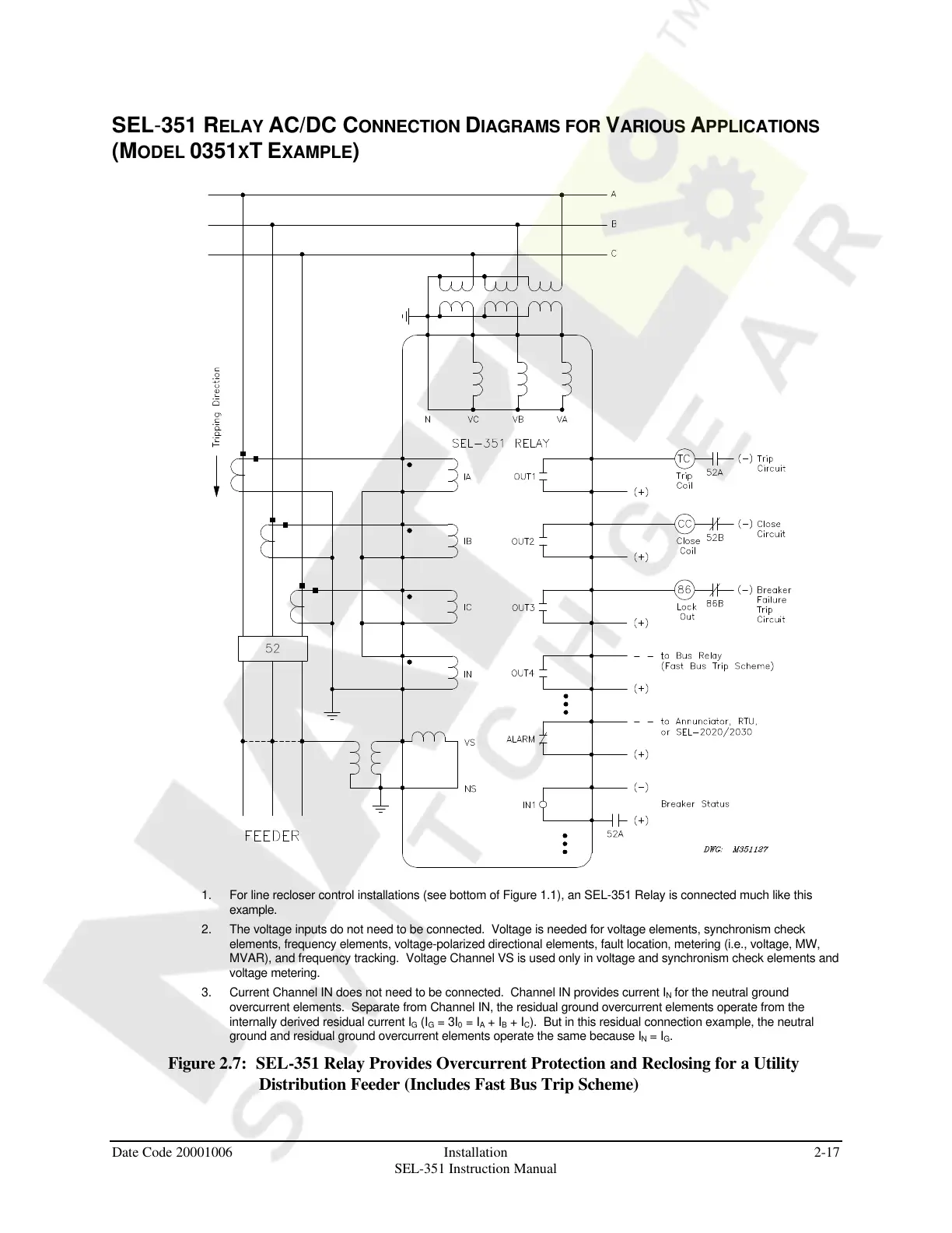
1. For line recloser control installations (see bottom of Figure 1.1), an SEL-351 Relay is connected much like this
example.
2. The voltage inputs do not need to be connected. Voltage is needed for voltage elements, synchronism check
elements, frequency elements, voltage-polarized directional elements, fault location, metering (i.e., voltage, MW,
MVAR), and frequency tracking. Voltage Channel VS is used only in voltage and synchronism check elements and
voltage metering.
3. Current Channel IN does not need to be connected. Channel IN provides current I
N
for the neutral ground
overcurrent elements. Separate from Channel IN, the residual ground overcurrent elements operate from the
internally derived residual current I
G
(I
G
= 3I
0
= I
A
+ I
B
+ I
C
). But in this residual connection example, the neutral
ground and residual ground overcurrent elements operate the same because I
N
= I
G
.
Figure 2.7: SEL-351 Relay Provides Overcurrent Protection and Reclosing for a Utility
Distribution Feeder (Includes Fast Bus Trip Scheme)
Courtesy of NationalSwitchgear.com