Date Code 20001006 Setting SELOGIC
®
Control Equations G-3
SEL-351 Instruction Manual
the preceding phase time-overcurrent element example) are rather unique because they have a
Relay Word bit (e.g., 51PR) that asserts for the reset state of the element.
Relay Word bits are used in SELOGIC Control Equations, which are explained in the following
subsection.
SELOGIC CONTROL EQUATIONS
Many of the protection and control element logic inputs shown in the various figures in Section 3
through Section 8 are SELOGIC Control Equations (labeled “SELOGIC Settings” in most of the
Figures). SELOGIC Control Equations are set with combinations of Relay Word bits to accomplish
such functions as:
• tripping circuit breakers
• assigning functions to optoisolated inputs
• operating output contacts
• torque-controlling overcurrent elements
• switching active setting groups
• enabling/disabling reclosing
Traditional or advanced custom schemes can be created with SELOGIC Control Equations.
SELOGIC Control Equation Operators
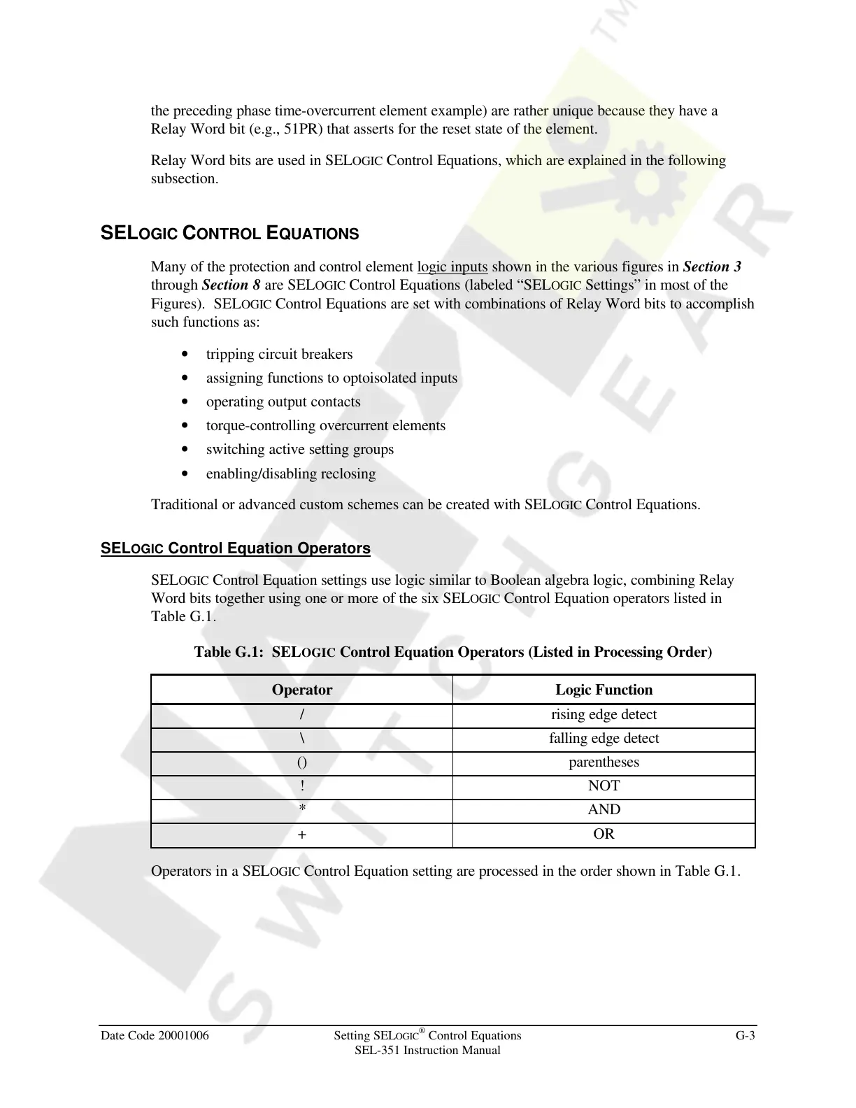
SELOGIC Control Equation settings use logic similar to Boolean algebra logic, combining Relay
Word bits together using one or more of the six SELOGIC Control Equation operators listed in
Table G.1.
Table G.1: SELOGIC Control Equation Operators (Listed in Processing Order)
Operator Logic Function
/ rising edge detect
\ falling edge detect
() parentheses
! NOT
* AND
+ OR
Operators in a SELOGIC Control Equation setting are processed in the order shown in Table G.1.
Courtesy of NationalSwitchgear.com