Date Code 20001006 Trip and Target Logic 5-29
SEL-351 Instruction Manual
FRONT-PANEL TARGET LEDS
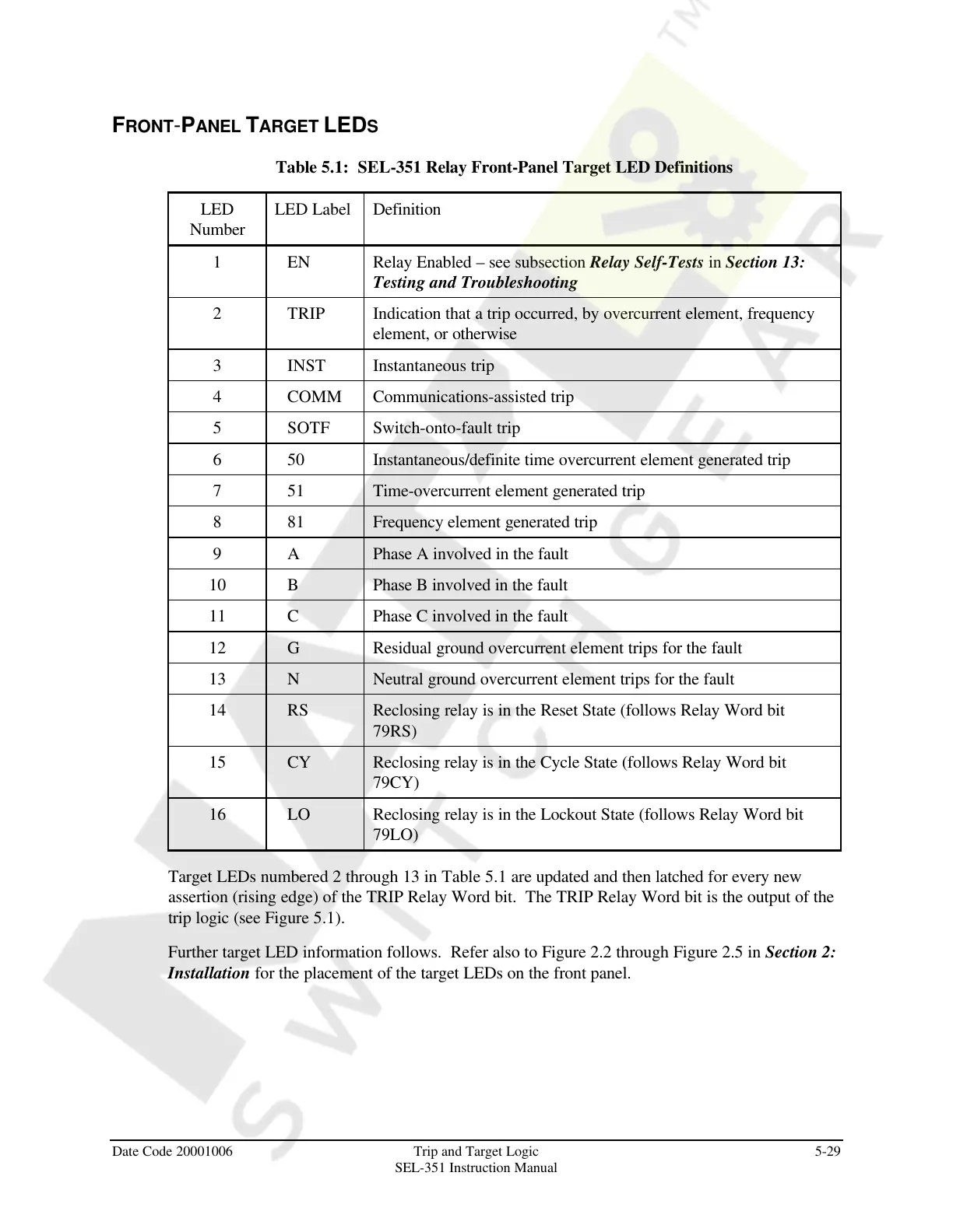
Table 5.1: SEL-351 Relay Front-Panel Target LED Definitions
LED
Number
LED Label Definition
1 EN Relay Enabled – see subsection Relay Self-Tests in Section 13:
Testing and Troubleshooting
2 TRIP Indication that a trip occurred, by overcurrent element, frequency
element, or otherwise
3 INST Instantaneous trip
4 COMM Communications-assisted trip
5 SOTF Switch-onto-fault trip
6 50 Instantaneous/definite time overcurrent element generated trip
7 51 Time-overcurrent element generated trip
8 81 Frequency element generated trip
9 A Phase A involved in the fault
10 B Phase B involved in the fault
11 C Phase C involved in the fault
12 G Residual ground overcurrent element trips for the fault
13 N Neutral ground overcurrent element trips for the fault
14 RS Reclosing relay is in the Reset State (follows Relay Word bit
79RS)
15 CY Reclosing relay is in the Cycle State (follows Relay Word bit
79CY)
16 LO Reclosing relay is in the Lockout State (follows Relay Word bit
79LO)
Target LEDs numbered 2 through 13 in Table 5.1 are updated and then latched for every new
assertion (rising edge) of the TRIP Relay Word bit. The TRIP Relay Word bit is the output of the
trip logic (see Figure 5.1).
Further target LED information follows. Refer also to Figure 2.2 through Figure 2.5 in Section 2:
Installation for the placement of the target LEDs on the front panel.
Courtesy of NationalSwitchgear.com
 Loading...


