7-40 Inputs, Outputs, Timers, and Other Control Logic Date Code 20001006
SEL-351 Instruction Manual
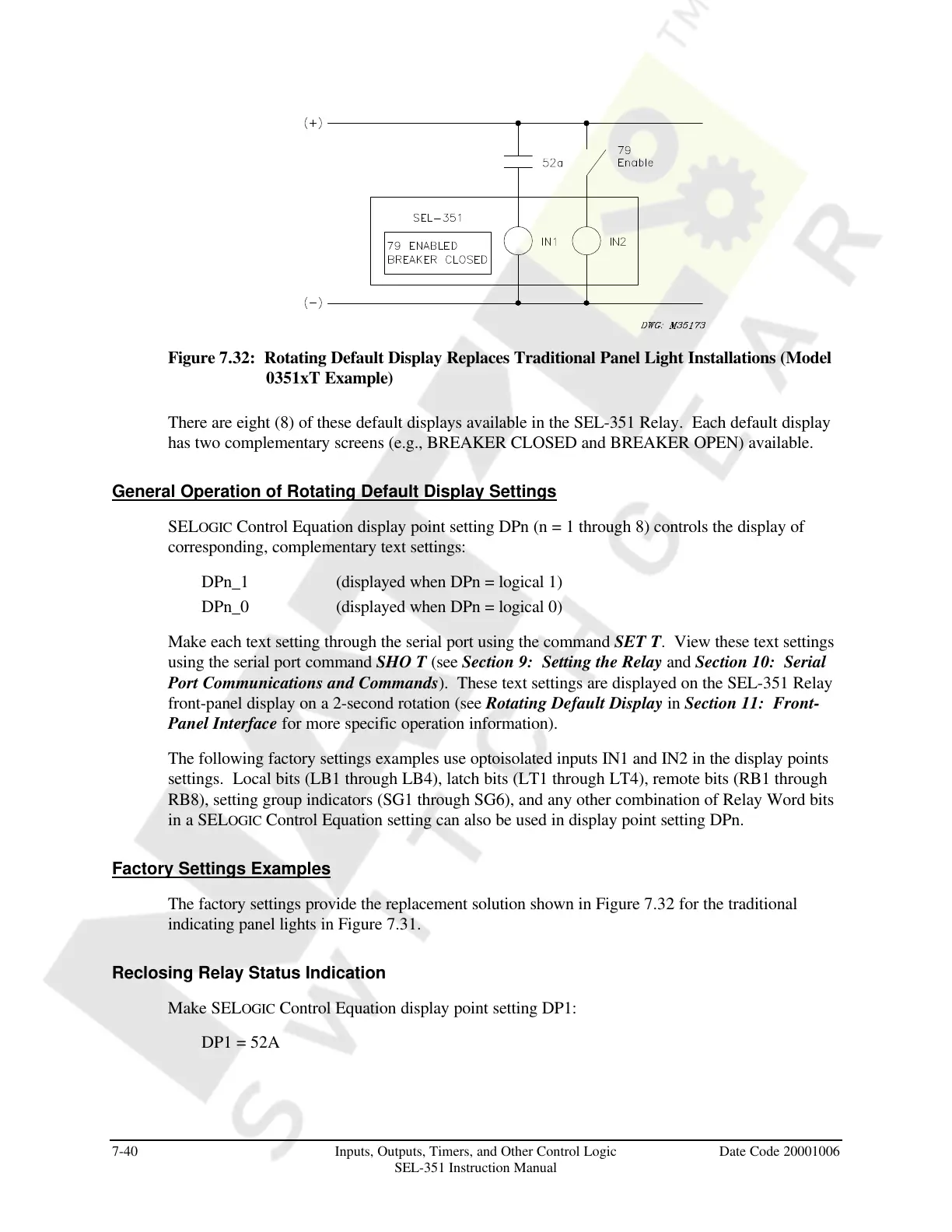
Figure 7.32: Rotating Default Display Replaces Traditional Panel Light Installations (Model
0351xT Example)
There are eight (8) of these default displays available in the SEL-351 Relay. Each default display
has two complementary screens (e.g., BREAKER CLOSED and BREAKER OPEN) available.
General Operation of Rotating Default Display Settings
SELOGIC Control Equation display point setting DPn (n = 1 through 8) controls the display of
corresponding, complementary text settings:
DPn_1 (displayed when DPn = logical 1)
DPn_0 (displayed when DPn = logical 0)
Make each text setting through the serial port using the command SET T. View these text settings
using the serial port command SHO T (see Section 9: Setting the Relay and Section 10: Serial
Port Communications and Commands). These text settings are displayed on the SEL-351 Relay
front-panel display on a 2-second rotation (see Rotating Default Display in Section 11: Front-
Panel Interface for more specific operation information).
The following factory settings examples use optoisolated inputs IN1 and IN2 in the display points
settings. Local bits (LB1 through LB4), latch bits (LT1 through LT4), remote bits (RB1 through
RB8), setting group indicators (SG1 through SG6), and any other combination of Relay Word bits
in a SELOGIC Control Equation setting can also be used in display point setting DPn.
Factory Settings Examples
The factory settings provide the replacement solution shown in Figure 7.32 for the traditional
indicating panel lights in Figure 7.31.
Reclosing Relay Status Indication
Make SELOGIC Control Equation display point setting DP1:
DP1 = 52A
Courtesy of NationalSwitchgear.com



 To Next Page