12-34 Standard Event Reports, Sag/Swell/Interruption Report, and SER Date Code 20001006
SEL-351 Instruction Manual
EXAMPLE SEQUENTIAL EVENTS RECORDER (SER) REPORT
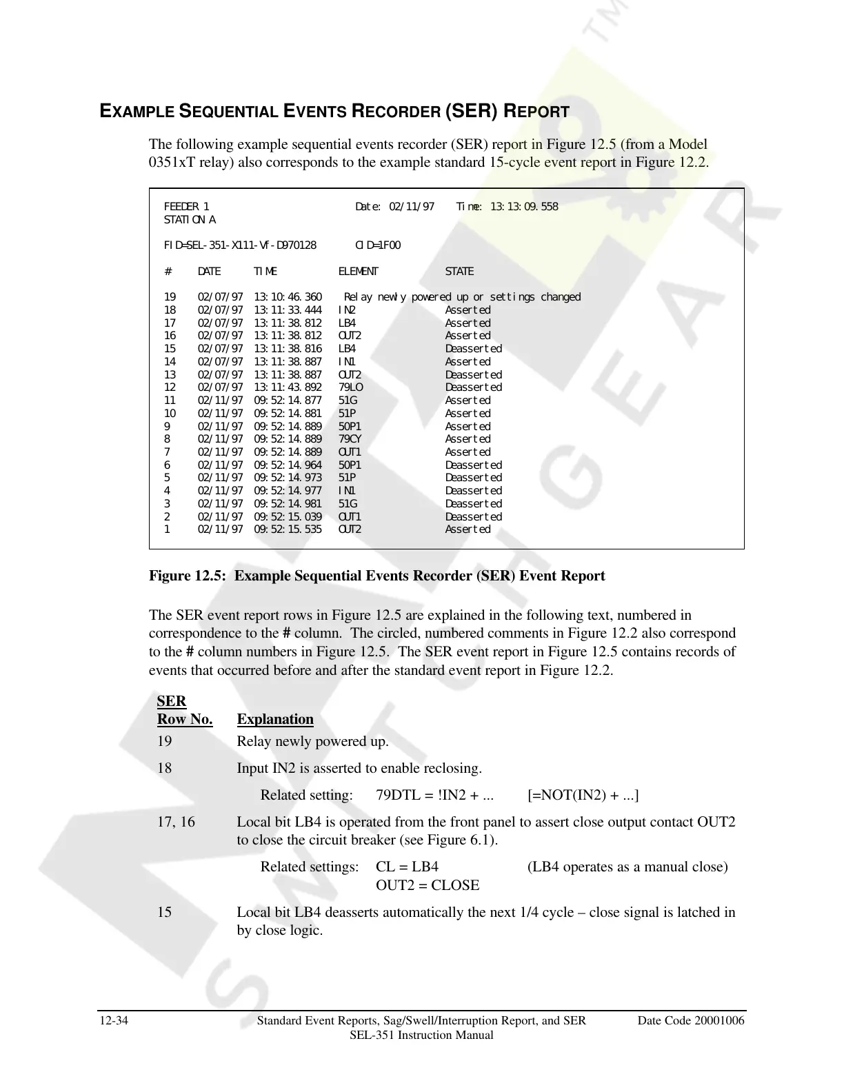
The following example sequential events recorder (SER) report in Figure 12.5 (from a Model
0351xT relay) also corresponds to the example standard 15-cycle event report in Figure 12.2.
FEEDER 1 Date: 02/11/97 Time: 13:13:09.558
STATION A
FID=SEL-351-X111-Vf-D970128 CID=1F00
# DATE TIME ELEMENT STATE
19 02/07/97 13:10:46.360 Relay newly powered up or settings changed
18 02/07/97 13:11:33.444 IN2 Asserted
17 02/07/97 13:11:38.812 LB4 Asserted
16 02/07/97 13:11:38.812 OUT2 Asserted
15 02/07/97 13:11:38.816 LB4 Deasserted
14 02/07/97 13:11:38.887 IN1 Asserted
13 02/07/97 13:11:38.887 OUT2 Deasserted
12 02/07/97 13:11:43.892 79LO Deasserted
11 02/11/97 09:52:14.877 51G Asserted
10 02/11/97 09:52:14.881 51P Asserted
9 02/11/97 09:52:14.889 50P1 Asserted
8 02/11/97 09:52:14.889 79CY Asserted
7 02/11/97 09:52:14.889 OUT1 Asserted
6 02/11/97 09:52:14.964 50P1 Deasserted
5 02/11/97 09:52:14.973 51P Deasserted
4 02/11/97 09:52:14.977 IN1 Deasserted
3 02/11/97 09:52:14.981 51G Deasserted
2 02/11/97 09:52:15.039 OUT1 Deasserted
1 02/11/97 09:52:15.535 OUT2 Asserted
Figure 12.5: Example Sequential Events Recorder (SER) Event Report
The SER event report rows in Figure 12.5 are explained in the following text, numbered in
correspondence to the # column. The circled, numbered comments in Figure 12.2 also correspond
to the # column numbers in Figure 12.5. The SER event report in Figure 12.5 contains records of
events that occurred before and after the standard event report in Figure 12.2.
SER
Row No. Explanation
19 Relay newly powered up.
18 Input IN2 is asserted to enable reclosing.
Related setting: 79DTL = !IN2 + ... [=NOT(IN2) + ...]
17, 16 Local bit LB4 is operated from the front panel to assert close output contact OUT2
to close the circuit breaker (see Figure 6.1).
Related settings: CL = LB4 (LB4 operates as a manual close)
OUT2 = CLOSE
15 Local bit LB4 deasserts automatically the next 1/4 cycle – close signal is latched in
by close logic.
Courtesy of NationalSwitchgear.com