Date Code 20001006 Inputs, Outputs, Timers, and Other Control Logic 7-15
SEL-351 Instruction Manual
SET1 = /IN4*!LT1 [= (rising edge of input IN4) AND NOT(LT1)]
RST1 = /IN4*LT1 [= (rising edge of input IN4) AND LT1]
79DTL = !LT1 [= NOT(LT1); drive-to-lockout setting]
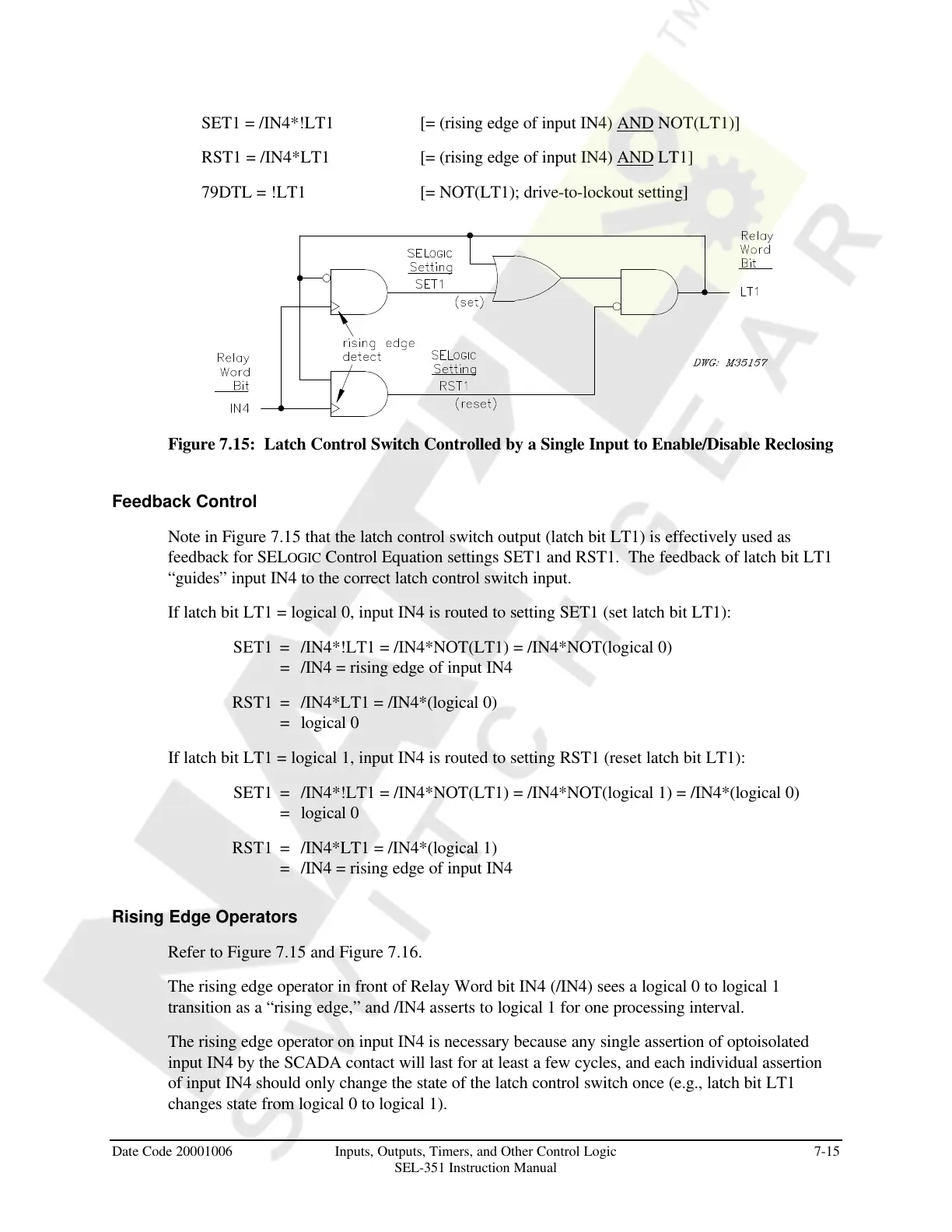
Figure 7.15: Latch Control Switch Controlled by a Single Input to Enable/Disable Reclosing
Feedback Control
Note in Figure 7.15 that the latch control switch output (latch bit LT1) is effectively used as
feedback for SELOGIC Control Equation settings SET1 and RST1. The feedback of latch bit LT1
“guides” input IN4 to the correct latch control switch input.
If latch bit LT1 = logical 0, input IN4 is routed to setting SET1 (set latch bit LT1):
SET1 = /IN4*!LT1 = /IN4*NOT(LT1) = /IN4*NOT(logical 0)
= /IN4 = rising edge of input IN4
RST1 = /IN4*LT1 = /IN4*(logical 0)
= logical 0
If latch bit LT1 = logical 1, input IN4 is routed to setting RST1 (reset latch bit LT1):
SET1 = /IN4*!LT1 = /IN4*NOT(LT1) = /IN4*NOT(logical 1) = /IN4*(logical 0)
= logical 0
RST1 = /IN4*LT1 = /IN4*(logical 1)
= /IN4 = rising edge of input IN4
Rising Edge Operators
Refer to Figure 7.15 and Figure 7.16.
The rising edge operator in front of Relay Word bit IN4 (/IN4) sees a logical 0 to logical 1
transition as a “rising edge,” and /IN4 asserts to logical 1 for one processing interval.
The rising edge operator on input IN4 is necessary because any single assertion of optoisolated
input IN4 by the SCADA contact will last for at least a few cycles, and each individual assertion
of input IN4 should only change the state of the latch control switch once (e.g., latch bit LT1
changes state from logical 0 to logical 1).
Courtesy of NationalSwitchgear.com