Date Code 20001006 Inputs, Outputs, Timers, and Other Control Logic 7-23
SEL-351 Instruction Manual
See Section 10: Serial Port Communications and Commands for more information on the serial
port GROUP command. See Section 11: Front-Panel Interface for more information on the
front-panel GROUP pushbutton.
Relay Disabled Momentarily During Active Setting Group Change
The relay is disabled for a few seconds while the relay is in the process of changing active setting
groups. Relay elements, timers, and logic are reset, unless indicated otherwise in specific logic
description [e.g., local bit (LB1 through LB8), remote bit (RB1 through RB8), and latch bit (LT1
through LT8) states are retained during a active setting group change]. The output contacts do not
change state until the relay enables in the new settings group and the SELOGIC Control Equations
are processed to determine the output contact status for the new group. For instance, if setting
OUT5 = logical 1 in Group 2, and setting OUT5 = logical 1 in Group 3, and the relay is switched
from Group 2 to Group 3, OUT5 stays energized before, during, and after the group change.
However, if the Group 3 setting was OUT5 = logical 0 instead, then OUT5 remains energized until
the relay enables in Group 3, solves the SELOGIC Control Equations, and causes OUT5 to
deenergize. See Figure 7.28, Figure 7.29, and Figure 7.30 for examples of output contacts in the
deenergized state (i.e., corresponding output contact coils deenergized).
Active Setting Group Switching Example 1
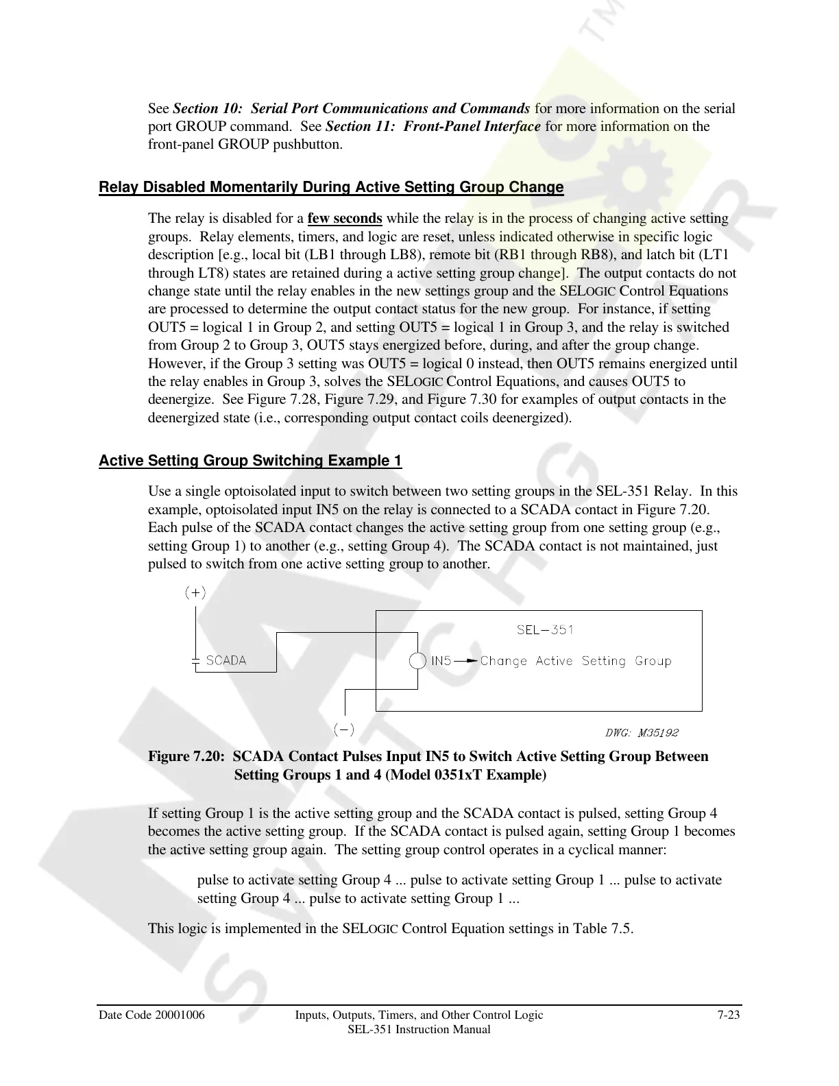
Use a single optoisolated input to switch between two setting groups in the SEL-351 Relay. In this
example, optoisolated input IN5 on the relay is connected to a SCADA contact in Figure 7.20.
Each pulse of the SCADA contact changes the active setting group from one setting group (e.g.,
setting Group 1) to another (e.g., setting Group 4). The SCADA contact is not maintained, just
pulsed to switch from one active setting group to another.
Figure 7.20: SCADA Contact Pulses Input IN5 to Switch Active Setting Group Between
Setting Groups 1 and 4 (Model 0351xT Example)
If setting Group 1 is the active setting group and the SCADA contact is pulsed, setting Group 4
becomes the active setting group. If the SCADA contact is pulsed again, setting Group 1 becomes
the active setting group again. The setting group control operates in a cyclical manner:
pulse to activate setting Group 4 ... pulse to activate setting Group 1 ... pulse to activate
setting Group 4 ... pulse to activate setting Group 1 ...
This logic is implemented in the SELOGIC Control Equation settings in Table 7.5.
Courtesy of NationalSwitchgear.com