7-4 Inputs, Outputs, Timers, and Other Control Logic Date Code 20001006
SEL-351 Instruction Manual
The relay processing interval is 1/4-cycle, so Relay Word bits IN1 through IN8 are updated every
1/4-cycle. The optoisolated input status may have made it through the pickup/dropout debounce
timer (for settings less than 1/4-cycle) because these timers run each 1/16-cycle, but Relay Word
bits IN1 through IN8 are updated every 1/4-cycle.
If more than 1 cycle of debounce is needed, run Relay Word bit INn (n = 1 through 8) through a
SELOGIC Control Equation variable timer and use the output of the timer for input functions (see
Figure 7.25 and Figure 7.26).
Input Functions
There are no optoisolated input settings such as:
IN1 =
IN2 =
Optoisolated inputs IN1 through IN8 receive their function by how their corresponding Relay
Word bits IN1 through IN8 are used in SELOGIC Control Equations.
Factory Settings Examples
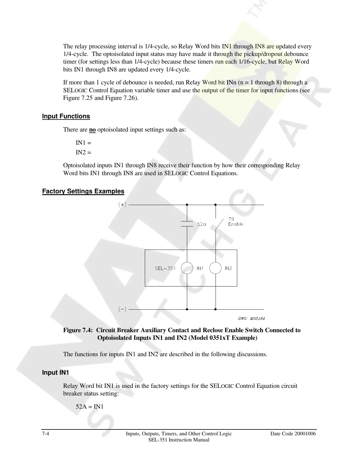
Figure 7.4: Circuit Breaker Auxiliary Contact and Reclose Enable Switch Connected to
Optoisolated Inputs IN1 and IN2 (Model 0351xT Example)
The functions for inputs IN1 and IN2 are described in the following discussions.
Input IN1
Relay Word bit IN1 is used in the factory settings for the SELOGIC Control Equation circuit
breaker status setting:
52A = IN1
Courtesy of NationalSwitchgear.com