Date Code 20001006 Trip and Target Logic 5-15
SEL-351 Instruction Manual
PT1 – Received Permissive Trip Signal(s)
In two-terminal line POTT applications, a permissive trip signal is received from one remote
terminal. One optoisolated input on the SEL-351 Relay (e.g., input IN4) is driven by a
communications equipment receiver output (see Figure 5.8). Make SELOGIC Control Equation
setting PT1:
PT1 = IN4 (two-terminal line application)
In three-terminal line POTT applications, permissive trip signals are received from two remote
terminals. Two optoisolated inputs on the SEL-351 Relay (e.g., input IN4 and IN6) are driven by
communications equipment receiver outputs (see Figure 5.9). Make SELOGIC Control Equation
setting PT1 as follows:
PT1 = IN4 * IN6 (three-terminal line application)
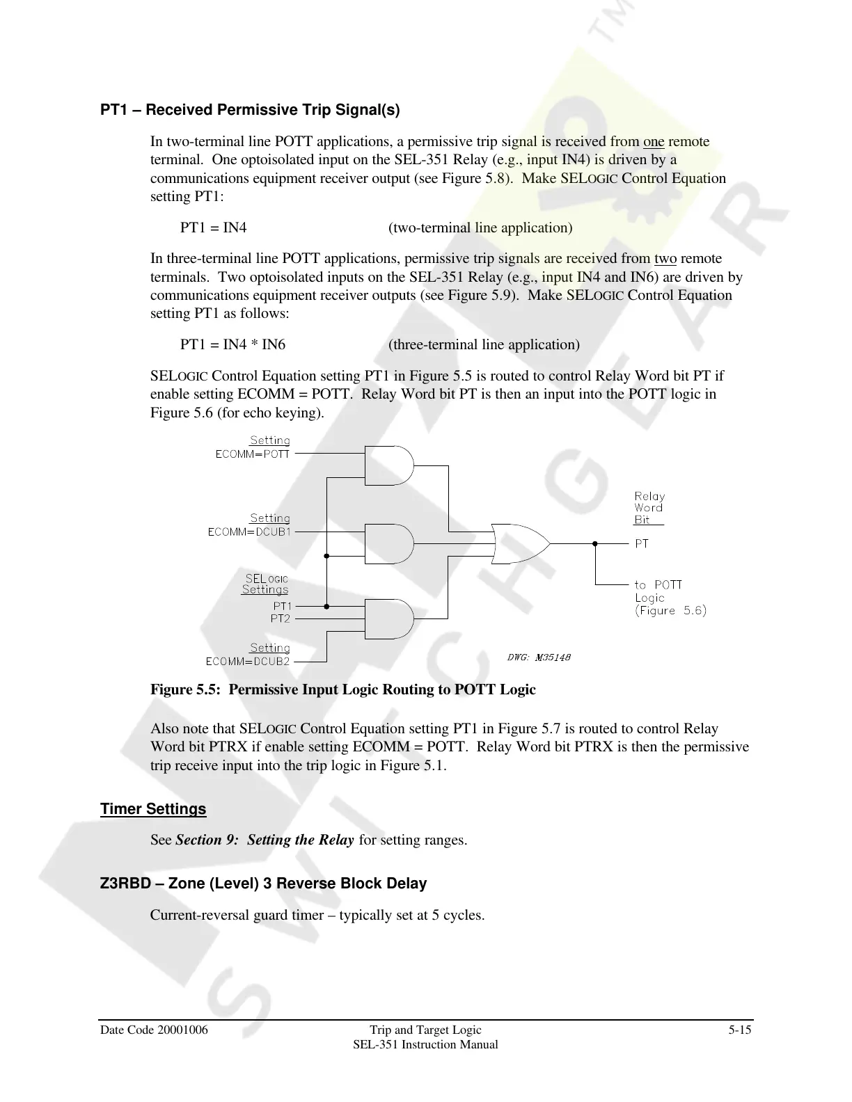
SELOGIC Control Equation setting PT1 in Figure 5.5 is routed to control Relay Word bit PT if
enable setting ECOMM = POTT. Relay Word bit PT is then an input into the POTT logic in
Figure 5.6 (for echo keying).
Figure 5.5: Permissive Input Logic Routing to POTT Logic
Also note that SELOGIC Control Equation setting PT1 in Figure 5.7 is routed to control Relay
Word bit PTRX if enable setting ECOMM = POTT. Relay Word bit PTRX is then the permissive
trip receive input into the trip logic in Figure 5.1.
Timer Settings
See Section 9: Setting the Relay for setting ranges.
Z3RBD – Zone (Level) 3 Reverse Block Delay
Current-reversal guard timer – typically set at 5 cycles.
Courtesy of NationalSwitchgear.com