10-2 Serial Port Communications and Commands Date Code 20001006
SEL-351 Instruction Manual
PORT CONNECTOR AND COMMUNICATIONS CABLES
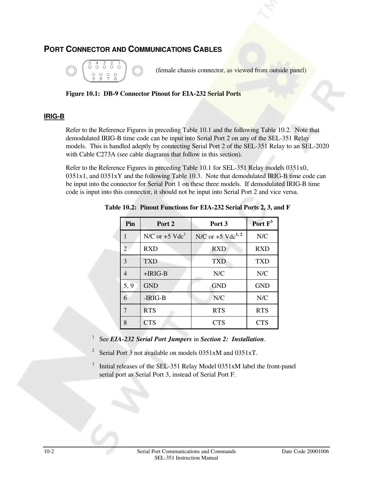
Figure 10.1: DB-9 Connector Pinout for EIA-232 Serial Ports
IRIG-B
Refer to the Reference Figures in preceding Table 10.1 and the following Table 10.2. Note that
demodulated IRIG-B time code can be input into Serial Port 2 on any of the SEL-351 Relay
models. This is handled adeptly by connecting Serial Port 2 of the SEL-351 Relay to an SEL-2020
with Cable C273A (see cable diagrams that follow in this section).
Refer to the Reference Figures in preceding Table 10.1 for SEL-351 Relay models 0351x0,
0351x1, and 0351xY and the following Table 10.3. Note that demodulated IRIG-B time code can
be input into the connector for Serial Port 1 on these three models. If demodulated IRIG-B time
code is input into this connector, it should not be input into Serial Port 2 and vice versa.
Table 10.2: Pinout Functions for EIA-232 Serial Ports 2, 3, and F
Pin Port 2 Port 3 Port F
3
1 N/C or +5 Vdc
1
N/C or +5 Vdc
1, 2
N/C
2 RXD RXD RXD
3 TXD TXD TXD
4 +IRIG-B N/C N/C
5, 9 GND GND GND
6 -IRIG-B N/C N/C
7 RTS RTS RTS
8 CTS CTS CTS
1
See EIA-232 Serial Port Jumpers in Section 2: Installation.
2
Serial Port 3 not available on models 0351xM and 0351xT.
3
Initial releases of the SEL-351 Relay Model 0351xM label the front-panel
serial port as Serial Port 3, instead of Serial Port F.
(female chassis connector, as viewed from outside panel)
Courtesy of NationalSwitchgear.com