Date Code 20001006 Overcurrent, Voltage, Synchronism Check, Frequency, and Power Elements 3-3
SEL-351 Instruction Manual
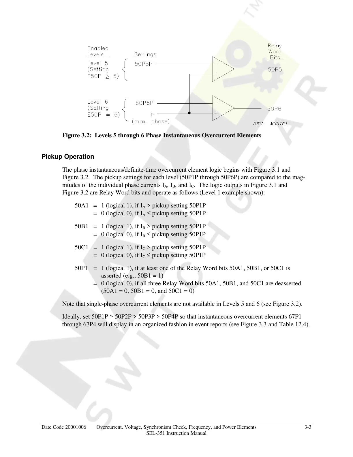
Figure 3.2: Levels 5 through 6 Phase Instantaneous Overcurrent Elements
Pickup Operation
The phase instantaneous/definite-time overcurrent element logic begins with Figure 3.1 and
Figure 3.2. The pickup settings for each level (50P1P through 50P6P) are compared to the mag-
nitudes of the individual phase currents I
A
, I
B
, and I
C
. The logic outputs in Figure 3.1 and
Figure 3.2 are Relay Word bits and operate as follows (Level 1 example shown):
50A1 = 1 (logical 1), if I
A
> pickup setting 50P1P
= 0 (logical 0), if I
A
≤ pickup setting 50P1P
50B1 = 1 (logical 1), if I
B
> pickup setting 50P1P
= 0 (logical 0), if I
B
≤ pickup setting 50P1P
50C1 = 1 (logical 1), if I
C
> pickup setting 50P1P
= 0 (logical 0), if I
C
≤ pickup setting 50P1P
50P1 = 1 (logical 1), if at least one of the Relay Word bits 50A1, 50B1, or 50C1 is
asserted (e.g., 50B1 = 1)
= 0 (logical 0), if all three Relay Word bits 50A1, 50B1, and 50C1 are deasserted
(50A1 = 0, 50B1 = 0, and 50C1 = 0)
Note that single-phase overcurrent elements are not available in Levels 5 and 6 (see Figure 3.2).
Ideally, set 50P1P > 50P2P > 50P3P > 50P4P so that instantaneous overcurrent elements 67P1
through 67P4 will display in an organized fashion in event reports (see Figure 3.3 and Table 12.4).
Courtesy of NationalSwitchgear.com