Date Code 20001006 Trip and Target Logic 5-27
SEL-351 Instruction Manual
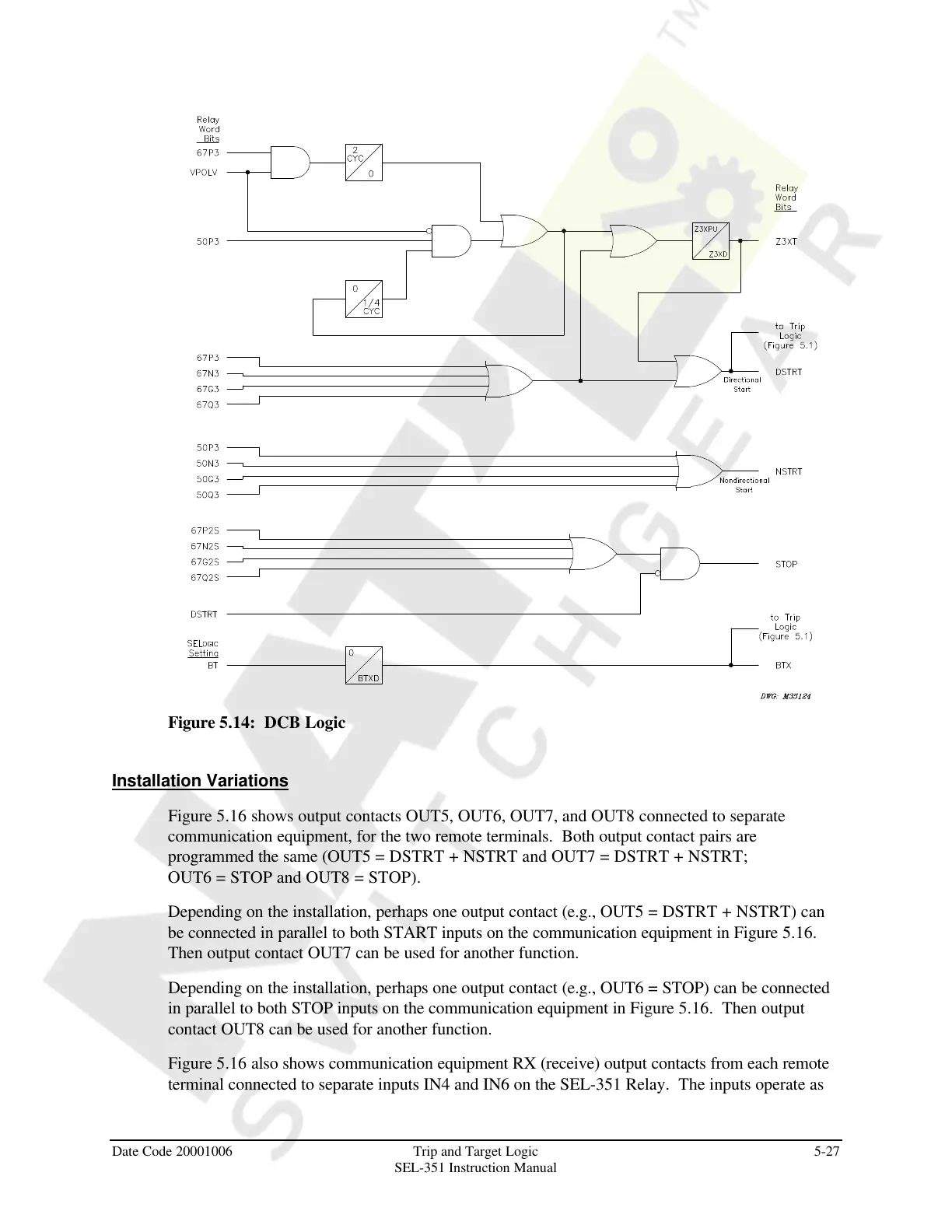
Figure 5.14: DCB Logic
Installation Variations
Figure 5.16 shows output contacts OUT5, OUT6, OUT7, and OUT8 connected to separate
communication equipment, for the two remote terminals. Both output contact pairs are
programmed the same (OUT5 = DSTRT + NSTRT and OUT7 = DSTRT + NSTRT;
OUT6 = STOP and OUT8 = STOP).
Depending on the installation, perhaps one output contact (e.g., OUT5 = DSTRT + NSTRT) can
be connected in parallel to both START inputs on the communication equipment in Figure 5.16.
Then output contact OUT7 can be used for another function.
Depending on the installation, perhaps one output contact (e.g., OUT6 = STOP) can be connected
in parallel to both STOP inputs on the communication equipment in Figure 5.16. Then output
contact OUT8 can be used for another function.
Figure 5.16 also shows communication equipment RX (receive) output contacts from each remote
terminal connected to separate inputs IN4 and IN6 on the SEL-351 Relay. The inputs operate as
Courtesy of NationalSwitchgear.com


 To Next Page