5-28 Trip and Target Logic Date Code 20001006
SEL-351 Instruction Manual
block trip receive inputs for the two remote terminals and are used in the SELOGIC Control
Equation setting:
BT = IN4 + IN6
Depending on the installation, perhaps one input (e.g., IN4) can be connected in parallel to both
communication equipment RX (receive) output contacts in Figure 5.16. Then setting BT would be
programmed as:
BT = IN4
and input IN6 can be used for another function.
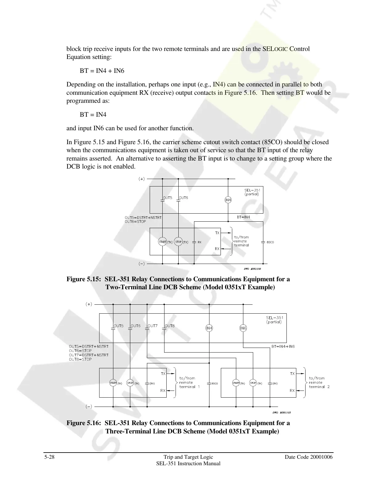
In Figure 5.15 and Figure 5.16, the carrier scheme cutout switch contact (85CO) should be closed
when the communications equipment is taken out of service so that the BT input of the relay
remains asserted. An alternative to asserting the BT input is to change to a setting group where the
DCB logic is not enabled.
Figure 5.15: SEL-351 Relay Connections to Communications Equipment for a
Two-Terminal Line DCB Scheme (Model 0351xT Example)
Figure 5.16: SEL-351 Relay Connections to Communications Equipment for a
Three-Terminal Line DCB Scheme (Model 0351xT Example)
Courtesy of NationalSwitchgear.com