7-32 Inputs, Outputs, Timers, and Other Control Logic Date Code 20001006
SEL-351 Instruction Manual
Factory Settings Example
In the factory SELOGIC Control Equation settings, a SELOGIC Control Equation timer is used for a
simple breaker failure scheme:
SV1 = TRIP
The TRIP Relay Word bit is run through a timer for breaker failure timing. Timer pickup setting
SV1PU is set to the breaker failure time (SV1PU = 12 cycles). Timer dropout setting SV1DO is
set for a 2-cycle dropout (SV1DO = 2 cycles). The output of the timer (Relay Word bit SV1T)
operates output contact OUT3.
OUT3 = SV1T
Additional Settings Example 1
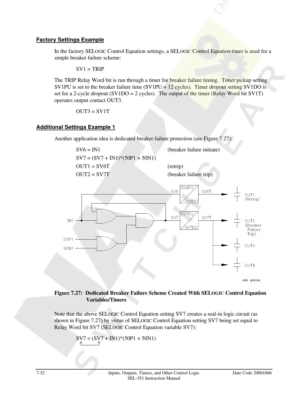
Another application idea is dedicated breaker failure protection (see Figure 7.27):
SV6 = IN1 (breaker failure initiate)
SV7 = (SV7 + IN1)*(50P1 + 50N1)
OUT1 = SV6T (retrip)
OUT2 = SV7T (breaker failure trip)
Figure 7.27: Dedicated Breaker Failure Scheme Created With SELOGIC Control Equation
Variables/Timers
Note that the above SELOGIC Control Equation setting SV7 creates a seal-in logic circuit (as
shown in Figure 7.27) by virtue of SELOGIC Control Equation setting SV7 being set equal to
Relay Word bit SV7 (SELOGIC Control Equation variable SV7):
SV7 = (SV7 + IN1)*(50P1 + 50N1)
Courtesy of NationalSwitchgear.com