5-24 Trip and Target Logic Date Code 20001006
SEL-351 Instruction Manual
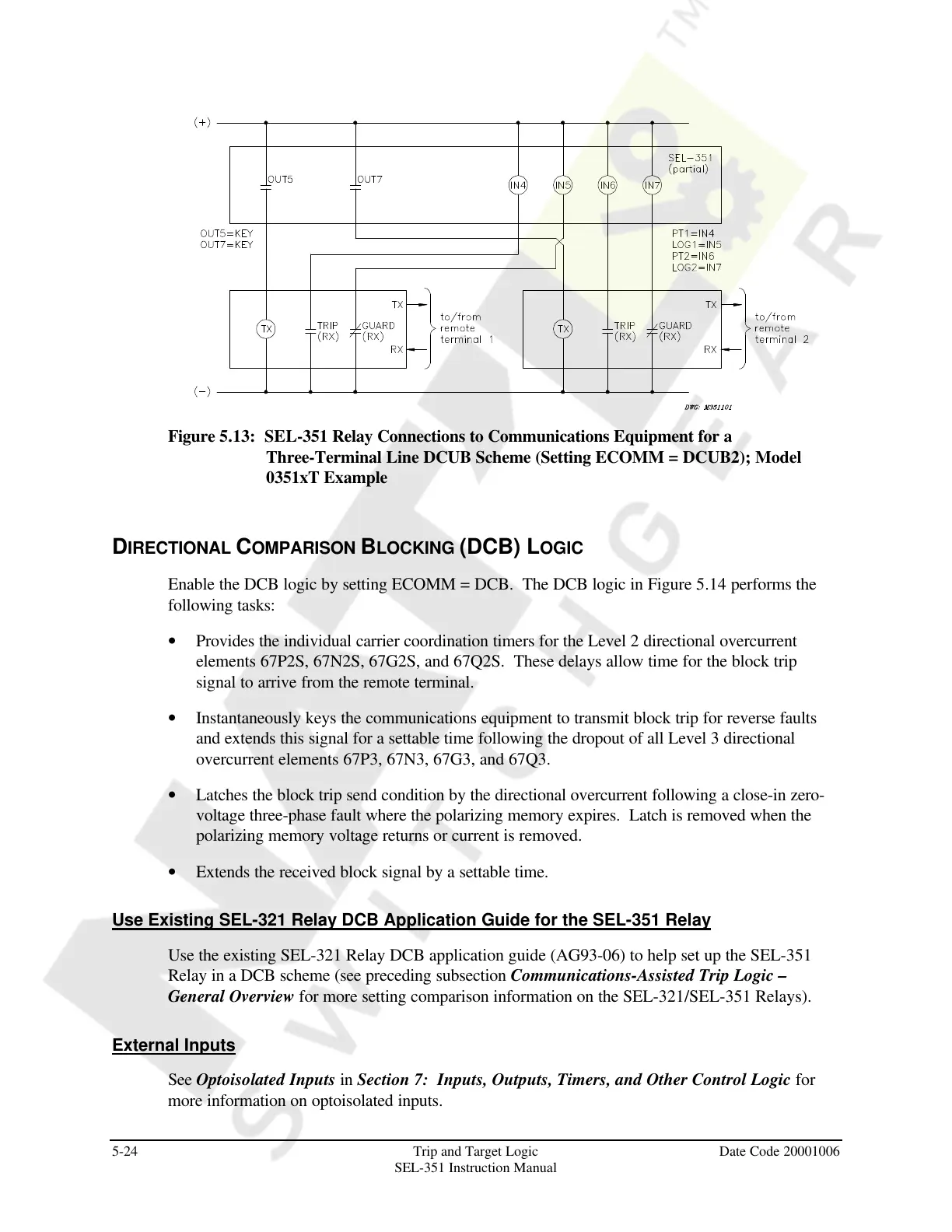
Figure 5.13: SEL-351 Relay Connections to Communications Equipment for a
Three-Terminal Line DCUB Scheme (Setting ECOMM = DCUB2); Model
0351xT Example
DIRECTIONAL COMPARISON BLOCKING (DCB) LOGIC
Enable the DCB logic by setting ECOMM = DCB. The DCB logic in Figure 5.14 performs the
following tasks:
• Provides the individual carrier coordination timers for the Level 2 directional overcurrent
elements 67P2S, 67N2S, 67G2S, and 67Q2S. These delays allow time for the block trip
signal to arrive from the remote terminal.
• Instantaneously keys the communications equipment to transmit block trip for reverse faults
and extends this signal for a settable time following the dropout of all Level 3 directional
overcurrent elements 67P3, 67N3, 67G3, and 67Q3.
• Latches the block trip send condition by the directional overcurrent following a close-in zero-
voltage three-phase fault where the polarizing memory expires. Latch is removed when the
polarizing memory voltage returns or current is removed.
• Extends the received block signal by a settable time.
Use Existing SEL-321 Relay DCB Application Guide for the SEL-351 Relay
Use the existing SEL-321 Relay DCB application guide (AG93-06) to help set up the SEL-351
Relay in a DCB scheme (see preceding subsection Communications-Assisted Trip Logic –
General Overview for more setting comparison information on the SEL-321/SEL-351 Relays).
External Inputs
See Optoisolated Inputs in Section 7: Inputs, Outputs, Timers, and Other Control Logic for
more information on optoisolated inputs.
Courtesy of NationalSwitchgear.com