Date Code 20001006 Inputs, Outputs, Timers, and Other Control Logic 7-7
SEL-351 Instruction Manual
The output of the local control switch in Figure 7.5 is a Relay Word bit LBn (n = 1 through 8),
called a local bit. The local control switch logic in Figure 7.5 repeats for each local bit LB1
through LB8. Use these local bits in SELOGIC Control Equations. For a given local control
switch, the local control switch positions are enabled by making corresponding label settings.
Table 7.1: Correspondence Between Local Control Switch Positions and Label Settings
Switch Position
Label
Setting Setting Definition Logic State
not applicable NLBn Name of Local Control
Switch
not applicable
ON SLBn “Set” Local bit LBn logical 1
OFF CLBn “Clear” Local bit LBn logical 0
MOMENTARY PLBn “Pulse” Local bit LBn logical 1 for one processing
interval
Note the first setting in Table 7.1 (NLBn) is the overall switch name setting. Make each label
setting through the serial port using the command SET T. View these settings using the serial port
command SHO T (see Section 9: Setting the Relay and Section 10: Serial Port
Communications and Commands).
Local Control Switch Types
Configure any local control switch as one of the following three switch types:
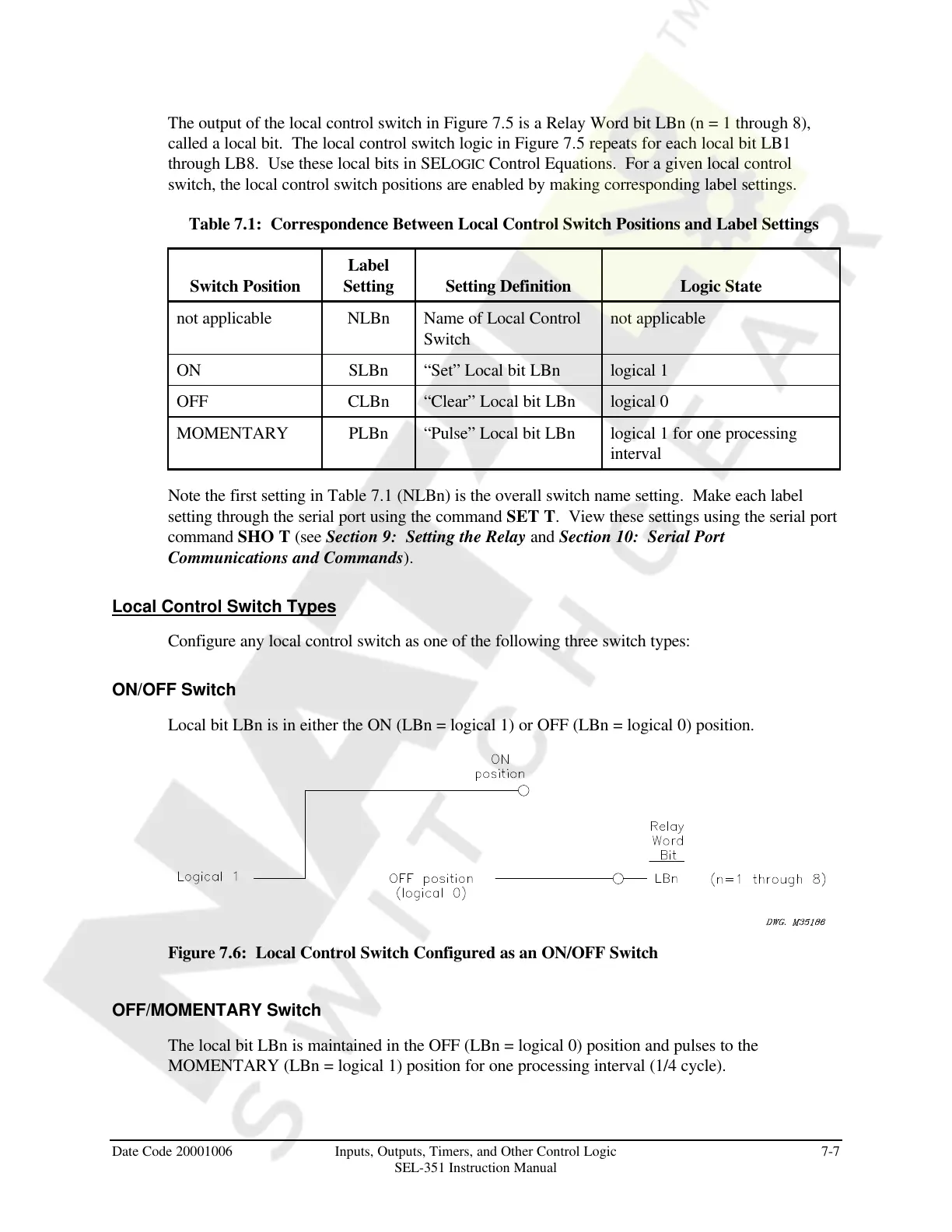
ON/OFF Switch
Local bit LBn is in either the ON (LBn = logical 1) or OFF (LBn = logical 0) position.
Figure 7.6: Local Control Switch Configured as an ON/OFF Switch
OFF/MOMENTARY Switch
The local bit LBn is maintained in the OFF (LBn = logical 0) position and pulses to the
MOMENTARY (LBn = logical 1) position for one processing interval (1/4 cycle).
Courtesy of NationalSwitchgear.com