8-4 Breaker Monitor, Metering, and Load Profile Functions Date Code 20001006
SEL-351 Instruction Manual
Breaker Monitor Setting Example
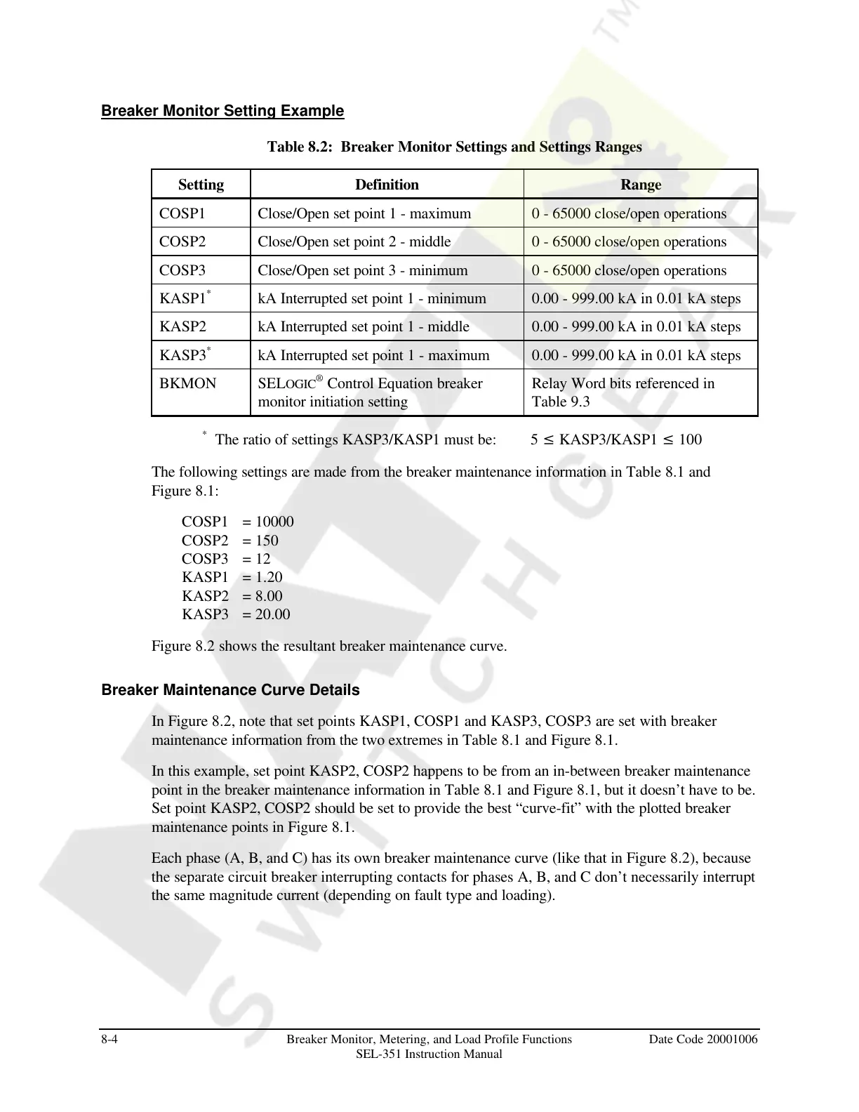
Table 8.2: Breaker Monitor Settings and Settings Ranges
Setting Definition Range
COSP1 Close/Open set point 1 - maximum 0 - 65000 close/open operations
COSP2 Close/Open set point 2 - middle 0 - 65000 close/open operations
COSP3 Close/Open set point 3 - minimum 0 - 65000 close/open operations
KASP1
*
kA Interrupted set point 1 - minimum 0.00 - 999.00 kA in 0.01 kA steps
KASP2 kA Interrupted set point 1 - middle 0.00 - 999.00 kA in 0.01 kA steps
KASP3
*
kA Interrupted set point 1 - maximum 0.00 - 999.00 kA in 0.01 kA steps
BKMON SELOGIC
®
Control Equation breaker
monitor initiation setting
Relay Word bits referenced in
Table 9.3
*
The ratio of settings KASP3/KASP1 must be: 5 £ KASP3/KASP1 £ 100
The following settings are made from the breaker maintenance information in Table 8.1 and
Figure 8.1:
COSP1 = 10000
COSP2 = 150
COSP3 = 12
KASP1 = 1.20
KASP2 = 8.00
KASP3 = 20.00
Figure 8.2 shows the resultant breaker maintenance curve.
Breaker Maintenance Curve Details
In Figure 8.2, note that set points KASP1, COSP1 and KASP3, COSP3 are set with breaker
maintenance information from the two extremes in Table 8.1 and Figure 8.1.
In this example, set point KASP2, COSP2 happens to be from an in-between breaker maintenance
point in the breaker maintenance information in Table 8.1 and Figure 8.1, but it doesn’t have to be.
Set point KASP2, COSP2 should be set to provide the best “curve-fit” with the plotted breaker
maintenance points in Figure 8.1.
Each phase (A, B, and C) has its own breaker maintenance curve (like that in Figure 8.2), because
the separate circuit breaker interrupting contacts for phases A, B, and C don’t necessarily interrupt
the same magnitude current (depending on fault type and loading).
Courtesy of NationalSwitchgear.com