3-58 Overcurrent, Voltage, Synchronism Check, Frequency, and Power Elements Date Code 20001006
SEL-351 Instruction Manual
Voltage Sag, Swell, and Interruption Elements Settings
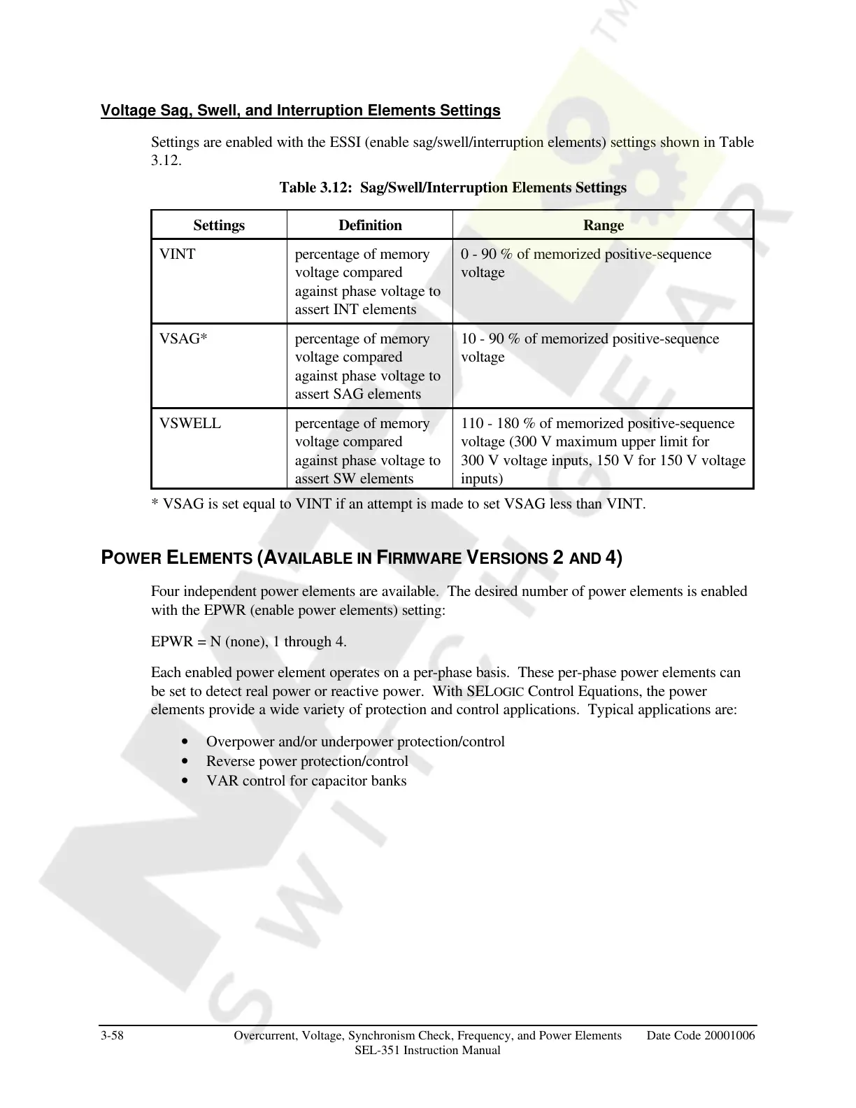
Settings are enabled with the ESSI (enable sag/swell/interruption elements) settings shown in Table
3.12.
Table 3.12: Sag/Swell/Interruption Elements Settings
Settings Definition Range
VINT percentage of memory
voltage compared
against phase voltage to
assert INT elements
0 - 90 % of memorized positive-sequence
voltage
VSAG* percentage of memory
voltage compared
against phase voltage to
assert SAG elements
10 - 90 % of memorized positive-sequence
voltage
VSWELL percentage of memory
voltage compared
against phase voltage to
assert SW elements
110 - 180 % of memorized positive-sequence
voltage (300 V maximum upper limit for
300 V voltage inputs, 150 V for 150 V voltage
inputs)
* VSAG is set equal to VINT if an attempt is made to set VSAG less than VINT.
POWER ELEMENTS (AVAILABLE IN FIRMWARE VERSIONS 2 AND 4)
Four independent power elements are available. The desired number of power elements is enabled
with the EPWR (enable power elements) setting:
EPWR = N (none), 1 through 4.
Each enabled power element operates on a per-phase basis. These per-phase power elements can
be set to detect real power or reactive power. With SELOGIC Control Equations, the power
elements provide a wide variety of protection and control applications. Typical applications are:
• Overpower and/or underpower protection/control
• Reverse power protection/control
• VAR control for capacitor banks
Courtesy of NationalSwitchgear.com