Date Code 20001006 Overcurrent, Voltage, Synchronism Check, Frequency, and Power Elements 3-61
SEL-351 Instruction Manual
DWG: M351197
Reactive
Power
Real
Power
PWR2P
(pickup)
PWR1P
(pickup)
Reactive
Power
PWR3P
(pickup)
PWR4P
(pickup)
Real
Power
52
SEL-
351
Set as Reactive Power Elements
reverse
(leading)
PWRA2
PWRB2
PWRC2
forward
(lagging)
PWRA1
PWRB1
PWRC1
52
SEL-
351
Set as Real Power Elements
reverse
PWRA4
PWRB4
PWRC4
forward
PWRA3
PWRB3
PWRC3
PWR4T =
-WATTS
(type)
PWR3T =
+WATTS
(type)
PWR2T =
-VARS
(type)
PWR1T =
+VARS
(type)
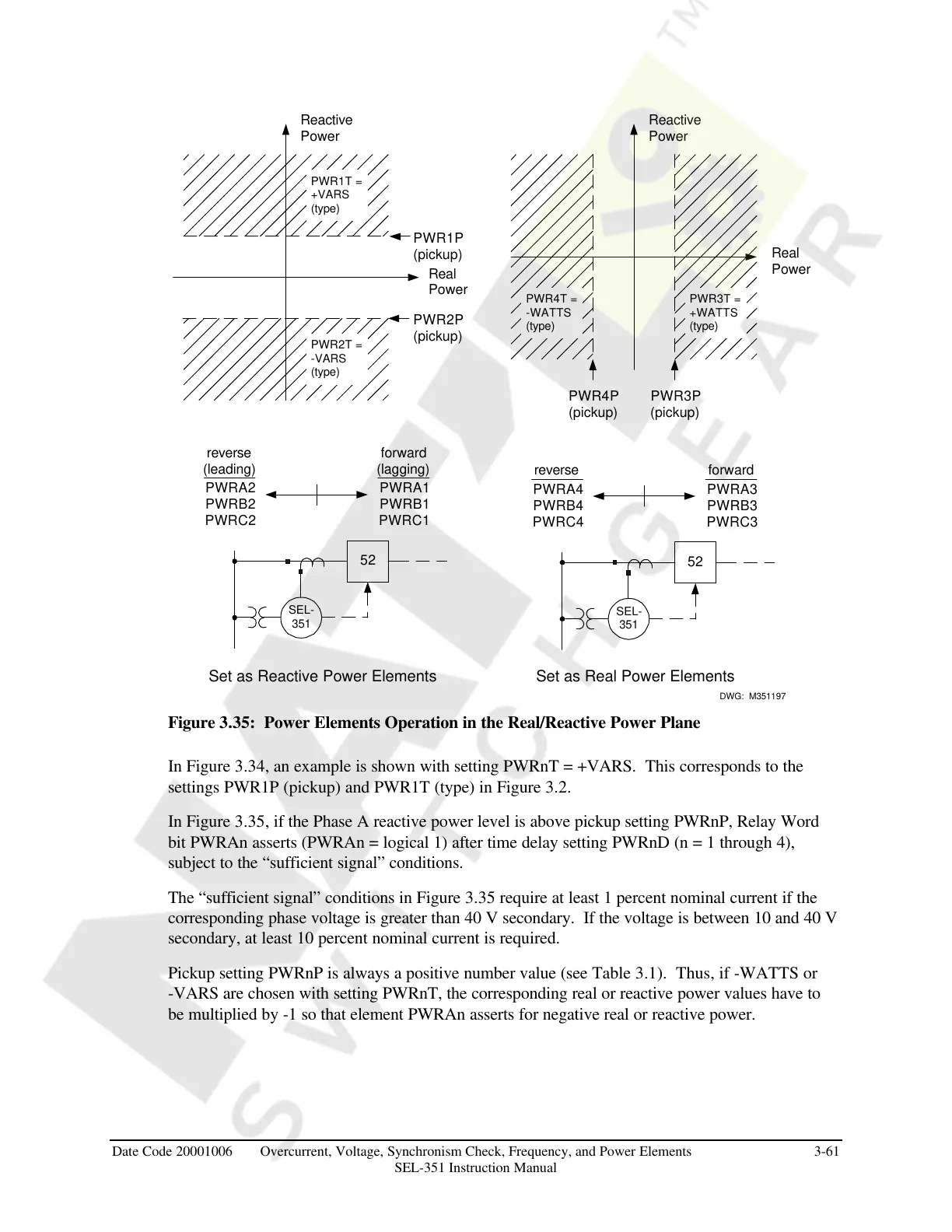
Figure 3.35: Power Elements Operation in the Real/Reactive Power Plane
In Figure 3.34, an example is shown with setting PWRnT = +VARS. This corresponds to the
settings PWR1P (pickup) and PWR1T (type) in Figure 3.2.
In Figure 3.35, if the Phase A reactive power level is above pickup setting PWRnP, Relay Word
bit PWRAn asserts (PWRAn = logical 1) after time delay setting PWRnD (n = 1 through 4),
subject to the “sufficient signal” conditions.
The “sufficient signal” conditions in Figure 3.35 require at least 1 percent nominal current if the
corresponding phase voltage is greater than 40 V secondary. If the voltage is between 10 and 40 V
secondary, at least 10 percent nominal current is required.
Pickup setting PWRnP is always a positive number value (see Table 3.1). Thus, if -WATTS or
-VARS are chosen with setting PWRnT, the corresponding real or reactive power values have to
be multiplied by -1 so that element PWRAn asserts for negative real or reactive power.
Courtesy of NationalSwitchgear.com


 To Next Page