4-8 Loss-of-Potential, Load Encroachment, and Directional Element Logic Date Code 20001006
SEL-351 Instruction Manual
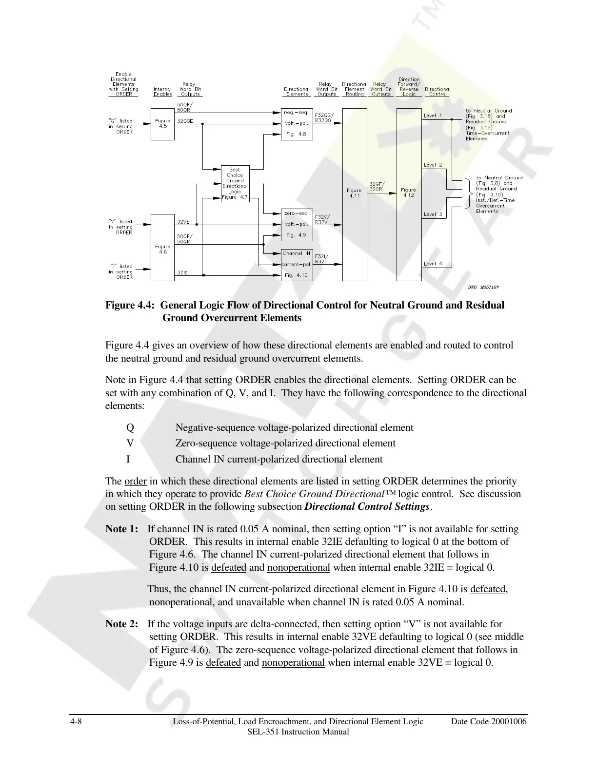
Figure 4.4: General Logic Flow of Directional Control for Neutral Ground and Residual
Ground Overcurrent Elements
Figure 4.4 gives an overview of how these directional elements are enabled and routed to control
the neutral ground and residual ground overcurrent elements.
Note in Figure 4.4 that setting ORDER enables the directional elements. Setting ORDER can be
set with any combination of Q, V, and I. They have the following correspondence to the directional
elements:
Q Negative-sequence voltage-polarized directional element
V Zero-sequence voltage-polarized directional element
I Channel IN current-polarized directional element
The order in which these directional elements are listed in setting ORDER determines the priority
in which they operate to provide Best Choice Ground Directional™ logic control. See discussion
on setting ORDER in the following subsection Directional Control Settings.
Note 1: If channel IN is rated 0.05 A nominal, then setting option “I” is not available for setting
ORDER. This results in internal enable 32IE defaulting to logical 0 at the bottom of
Figure 4.6. The channel IN current-polarized directional element that follows in
Figure 4.10 is defeated and nonoperational when internal enable 32IE = logical 0.
Thus, the channel IN current-polarized directional element in Figure 4.10 is defeated,
nonoperational, and unavailable when channel IN is rated 0.05 A nominal.
Note 2: If the voltage inputs are delta-connected, then setting option “V” is not available for
setting ORDER. This results in internal enable 32VE defaulting to logical 0 (see middle
of Figure 4.6). The zero-sequence voltage-polarized directional element that follows in
Figure 4.9 is defeated and nonoperational when internal enable 32VE = logical 0.
Courtesy of NationalSwitchgear.com