Date Code 20001006 Loss-of-Potential, Load Encroachment, and Directional Element Logic 4-11
SEL-351 Instruction Manual
then the corresponding Level 1 directional control output in Figure 4.12 asserts to logical 1. The
referenced Level 1 overcurrent elements in Figure 4.12 are then not controlled by the directional
control logic.
See the beginning of following subsection Directional Control Settings for discussion of the
operation of level direction settings DIR1 through DIR4 when the directional control enable setting
E32 is set to E32 = N.
In some applications, level direction settings DIR1 through DIR4 are not flexible enough in
assigning the desired direction for certain overcurrent elements. Subsection Directional Control
Provided by Torque Control Settings at the end of this section describes how to avoid this
limitation for special cases.
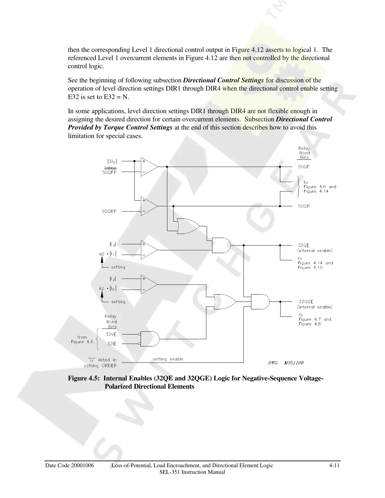
Figure 4.5: Internal Enables (32QE and 32QGE) Logic for Negative-Sequence Voltage-
Polarized Directional Elements
Courtesy of NationalSwitchgear.com
 Loading...


