Date Code 20001006 Inputs, Outputs, Timers, and Other Control Logic 7-13
SEL-351 Instruction Manual
See Appendix G: Setting SELOGIC Control Equations for more details on using the rising and
falling edge operators in SELOGIC Control Equations.
LATCH CONTROL SWITCHES
The latch control switch feature of this relay replaces latching relays. Traditional latching relays
maintain their output contact state — they are not dependent on dc voltage to maintain their output
contact state. For example, if a latching relay output contact is closed and then dc voltage is lost to
the panel, the latching relay output contact remains closed.
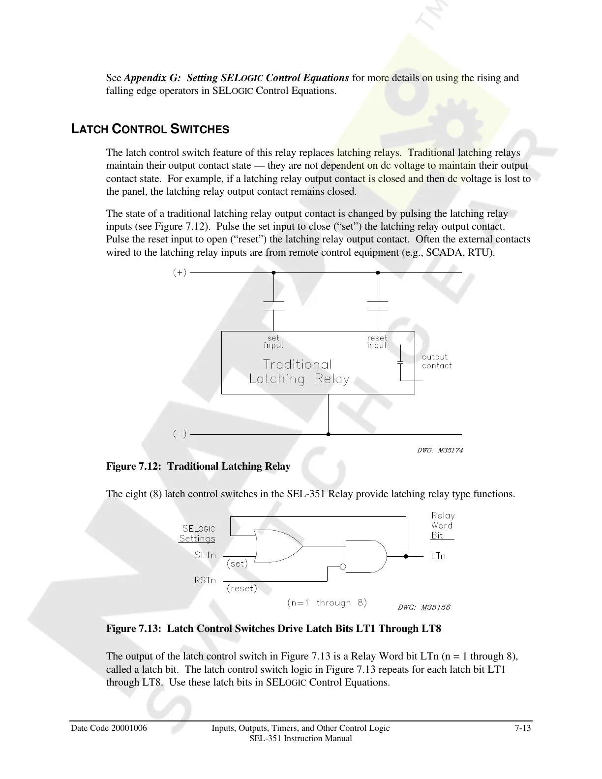
The state of a traditional latching relay output contact is changed by pulsing the latching relay
inputs (see Figure 7.12). Pulse the set input to close (“set”) the latching relay output contact.
Pulse the reset input to open (“reset”) the latching relay output contact. Often the external contacts
wired to the latching relay inputs are from remote control equipment (e.g., SCADA, RTU).
Figure 7.12: Traditional Latching Relay
The eight (8) latch control switches in the SEL-351 Relay provide latching relay type functions.
Figure 7.13: Latch Control Switches Drive Latch Bits LT1 Through LT8
The output of the latch control switch in Figure 7.13 is a Relay Word bit LTn (n = 1 through 8),
called a latch bit. The latch control switch logic in Figure 7.13 repeats for each latch bit LT1
through LT8. Use these latch bits in SELOGIC Control Equations.
Courtesy of NationalSwitchgear.com