Date Code 20001006 Inputs, Outputs, Timers, and Other Control Logic 7-27
SEL-351 Instruction Manual
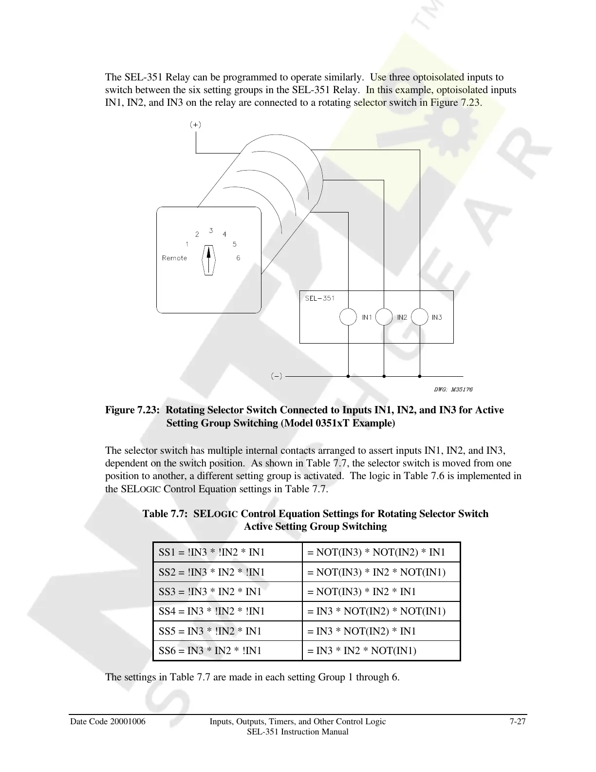
The SEL-351 Relay can be programmed to operate similarly. Use three optoisolated inputs to
switch between the six setting groups in the SEL-351 Relay. In this example, optoisolated inputs
IN1, IN2, and IN3 on the relay are connected to a rotating selector switch in Figure 7.23.
Figure 7.23: Rotating Selector Switch Connected to Inputs IN1, IN2, and IN3 for Active
Setting Group Switching (Model 0351xT Example)
The selector switch has multiple internal contacts arranged to assert inputs IN1, IN2, and IN3,
dependent on the switch position. As shown in Table 7.7, the selector switch is moved from one
position to another, a different setting group is activated. The logic in Table 7.6 is implemented in
the SELOGIC Control Equation settings in Table 7.7.
Table 7.7: SELOGIC Control Equation Settings for Rotating Selector Switch
Active Setting Group Switching
SS1 = !IN3 * !IN2 * IN1 = NOT(IN3) * NOT(IN2) * IN1
SS2 = !IN3 * IN2 * !IN1 = NOT(IN3) * IN2 * NOT(IN1)
SS3 = !IN3 * IN2 * IN1 = NOT(IN3) * IN2 * IN1
SS4 = IN3 * !IN2 * !IN1 = IN3 * NOT(IN2) * NOT(IN1)
SS5 = IN3 * !IN2 * IN1 = IN3 * NOT(IN2) * IN1
SS6 = IN3 * IN2 * !IN1 = IN3 * IN2 * NOT(IN1)
The settings in Table 7.7 are made in each setting Group 1 through 6.
Courtesy of NationalSwitchgear.com