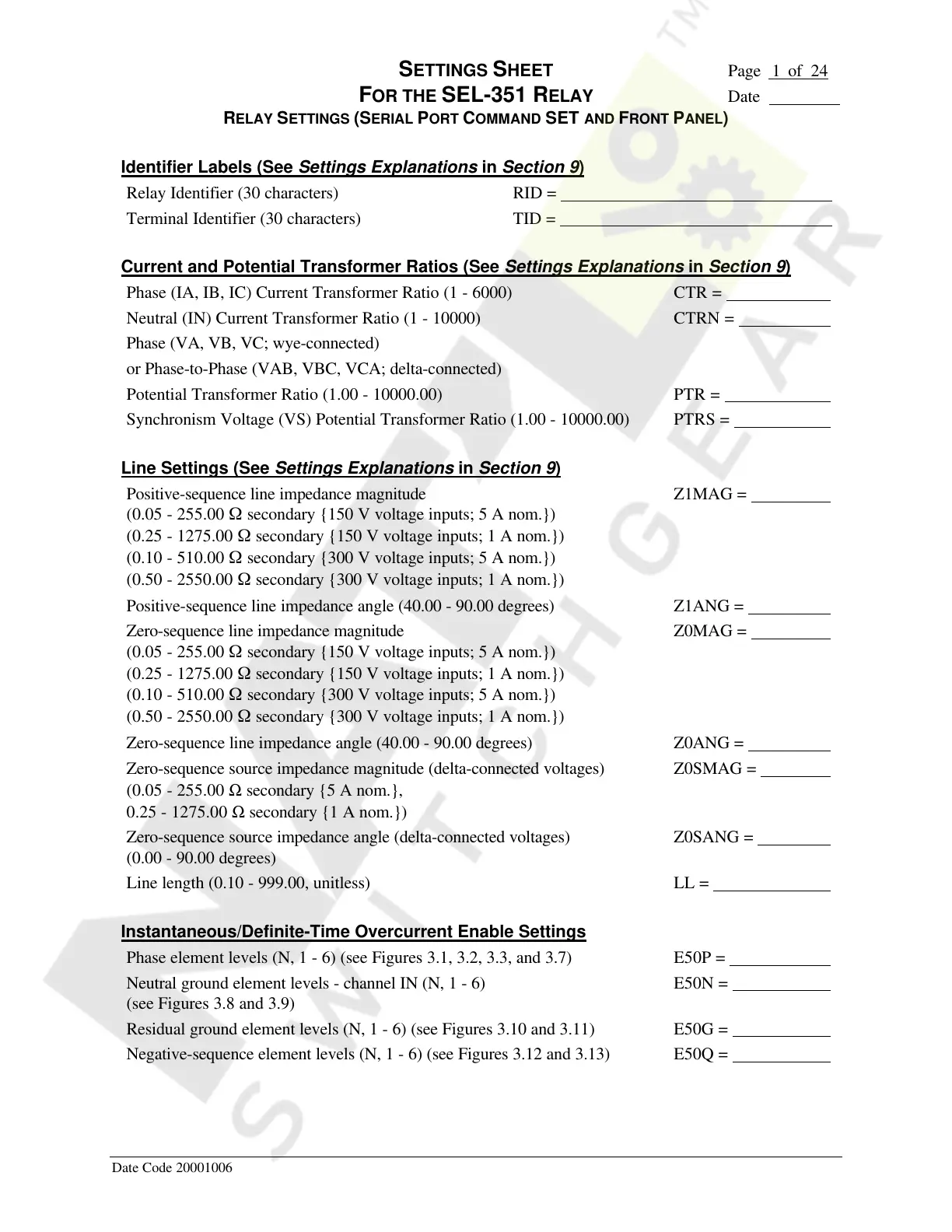
SETTINGS SHEET Page 1 of 24
FOR THE SEL-351 RELAY Date
RELAY SETTINGS (SERIAL PORT COMMAND SET AND FRONT PANEL)
Date Code 20001006
Identifier Labels (See Settings Explanations in Section 9)
Relay Identifier (30 characters) RID =
Terminal Identifier (30 characters) TID =
Current and Potential Transformer Ratios (See Settings Explanations in Section 9)
Phase (IA, IB, IC) Current Transformer Ratio (1 - 6000) CTR =
Neutral (IN) Current Transformer Ratio (1 - 10000) CTRN =
Phase (VA, VB, VC; wye-connected)
or Phase-to-Phase (VAB, VBC, VCA; delta-connected)
Potential Transformer Ratio (1.00 - 10000.00) PTR =
Synchronism Voltage (VS) Potential Transformer Ratio (1.00 - 10000.00) PTRS =
Line Settings (See Settings Explanations in Section 9)
Positive-sequence line impedance magnitude
(0.05 - 255.00 W secondary {150 V voltage inputs; 5 A nom.})
(0.25 - 1275.00 W secondary {150 V voltage inputs; 1 A nom.})
(0.10 - 510.00 W secondary {300 V voltage inputs; 5 A nom.})
(0.50 - 2550.00 W secondary {300 V voltage inputs; 1 A nom.})
Z1MAG =
Positive-sequence line impedance angle (40.00 - 90.00 degrees) Z1ANG =
Zero-sequence line impedance magnitude
(0.05 - 255.00 W secondary {150 V voltage inputs; 5 A nom.})
(0.25 - 1275.00 W secondary {150 V voltage inputs; 1 A nom.})
(0.10 - 510.00 W secondary {300 V voltage inputs; 5 A nom.})
(0.50 - 2550.00 W secondary {300 V voltage inputs; 1 A nom.})
Z0MAG =
Zero-sequence line impedance angle (40.00 - 90.00 degrees) Z0ANG =
Zero-sequence source impedance magnitude (delta-connected voltages)
(0.05 - 255.00 Ω secondary {5 A nom.},
0.25 - 1275.00 Ω secondary {1 A nom.})
Z0SMAG =
Zero-sequence source impedance angle (delta-connected voltages)
(0.00 - 90.00 degrees)
Z0SANG =
Line length (0.10 - 999.00, unitless) LL =
Instantaneous/Definite-Time Overcurrent Enable Settings
Phase element levels (N, 1 - 6) (see Figures 3.1, 3.2, 3.3, and 3.7) E50P =
Neutral ground element levels - channel IN (N, 1 - 6)
(see Figures 3.8 and 3.9)
E50N =
Residual ground element levels (N, 1 - 6) (see Figures 3.10 and 3.11) E50G =
Negative-sequence element levels (N, 1 - 6) (see Figures 3.12 and 3.13) E50Q =
Courtesy of NationalSwitchgear.com