Date Code 20001006 Front-Panel Interface 11-13
SEL-351 Instruction Manual
Display
Points
(SELOGIC
Control
Equation
Settings)
Example
Display
Point
States
Display Point
Label Settings
DP1 = IN2
DP2 = 52A
= logical 1
= logical 1
DP1_1 = 79 ENABLED
DP1_0 = 79 DISABLED
DP2_1 = BREAKER CLOSED
DP2_0 = BREAKER OPEN
DP1 = IN2
DP2 = 52A
= logical 0
= logical 1
DP1_1 = 79 ENABLED
DP1_0 = 79 DISABLED
DP2_1 = BREAKER CLOSED
DP2_0 = BREAKER OPEN
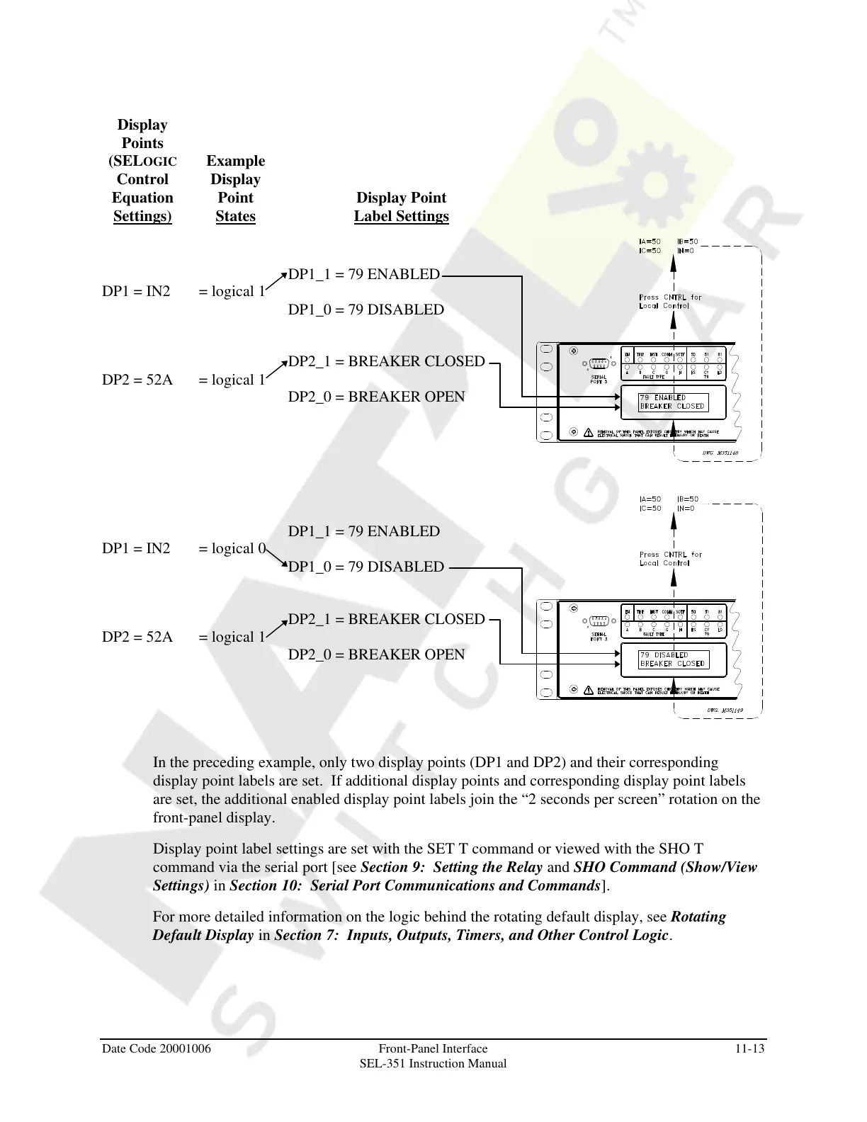
In the preceding example, only two display points (DP1 and DP2) and their corresponding
display point labels are set. If additional display points and corresponding display point labels
are set, the additional enabled display point labels join the “2 seconds per screen” rotation on the
front-panel display.
Display point label settings are set with the SET T command or viewed with the SHO T
command via the serial port [see Section 9: Setting the Relay and SHO Command (Show/View
Settings) in Section 10: Serial Port Communications and Commands].
For more detailed information on the logic behind the rotating default display, see Rotating
Default Display in Section 7: Inputs, Outputs, Timers, and Other Control Logic.
Courtesy of NationalSwitchgear.com