G-12 Setting SELOGIC
®
Control Equations Date Code 20001006
SEL-351 Instruction Manual
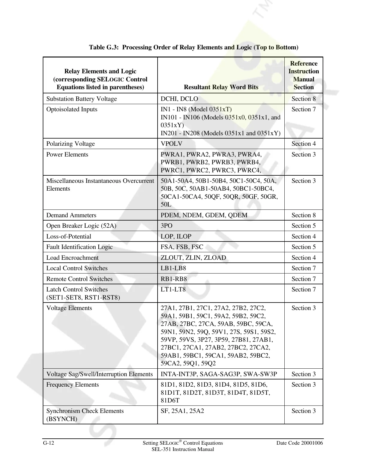
Table G.3: Processing Order of Relay Elements and Logic (Top to Bottom)
Relay Elements and Logic
(corresponding SELOGIC Control
Equations listed in parentheses) Resultant Relay Word Bits
Reference
Instruction
Manual
Section
Substation Battery Voltage DCHI, DCLO Section 8
Optoisolated Inputs IN1 - IN8 (Model 0351xT)
IN101 - IN106 (Models 0351x0, 0351x1, and
0351xY)
IN201 - IN208 (Models 0351x1 and 0351xY)
Section 7
Polarizing Voltage VPOLV Section 4
Power Elements PWRA1, PWRA2, PWRA3, PWRA4,
PWRB1, PWRB2, PWRB3, PWRB4,
PWRC1, PWRC2, PWRC3, PWRC4,
Section 3
Miscellaneous Instantaneous Overcurrent
Elements
50A1-50A4, 50B1-50B4, 50C1-50C4, 50A,
50B, 50C, 50AB1-50AB4, 50BC1-50BC4,
50CA1-50CA4, 50QF, 50QR, 50GF, 50GR,
50L
Section 3
Demand Ammeters PDEM, NDEM, GDEM, QDEM Section 8
Open Breaker Logic (52A) 3PO Section 5
Loss-of-Potential LOP, ILOP Section 4
Fault Identification Logic FSA, FSB, FSC Section 5
Load Encroachment ZLOUT, ZLIN, ZLOAD Section 4
Local Control Switches LB1-LB8 Section 7
Remote Control Switches RB1-RB8 Section 7
Latch Control Switches
(SET1-SET8, RST1-RST8)
LT1-LT8 Section 7
Voltage Elements 27A1, 27B1, 27C1, 27A2, 27B2, 27C2,
59A1, 59B1, 59C1, 59A2, 59B2, 59C2,
27AB, 27BC, 27CA, 59AB, 59BC, 59CA,
59N1, 59N2, 59Q, 59V1, 27S, 59S1, 59S2,
59VP, 59VS, 3P27, 3P59, 27B81, 27AB1,
27BC1, 27CA1, 27AB2, 27BC2, 27CA2,
59AB1, 59BC1, 59CA1, 59AB2, 59BC2,
59CA2, 59Q1, 59Q2
Section 3
Voltage Sag/Swell/Interruption Elements INTA-INT3P, SAGA-SAG3P, SWA-SW3P Section 3
Frequency Elements 81D1, 81D2, 81D3, 81D4, 81D5, 81D6,
81D1T, 81D2T, 81D3T, 81D4T, 81D5T,
81D6T
Section 3
Synchronism Check Elements
(BSYNCH)
SF, 25A1, 25A2 Section 3
Courtesy of NationalSwitchgear.com



 To Next Page