Date Code 20001006 Manual Change Information v
SEL-351 Instruction Manual
Revision
Date
Summary of Revisions
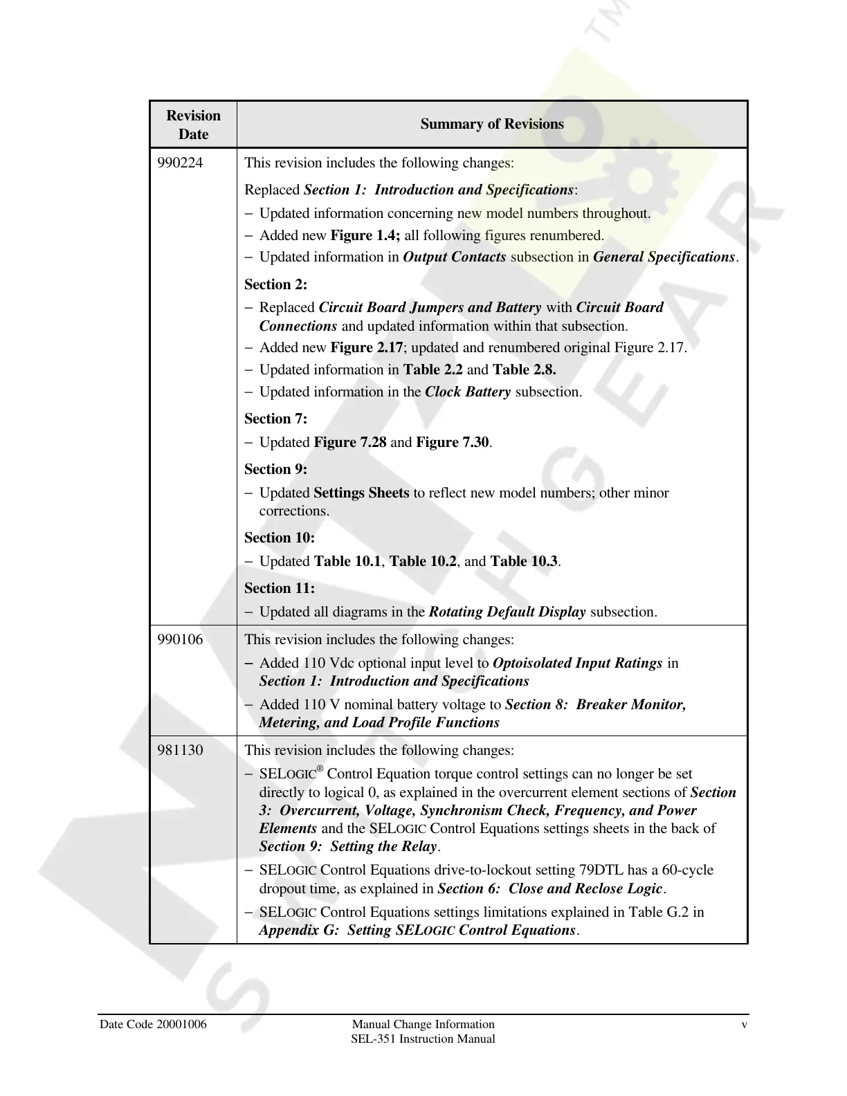
990224 This revision includes the following changes:
Replaced Section 1: Introduction and Specifications:
− Updated information concerning new model numbers throughout.
− Added new Figure 1.4; all following figures renumbered.
− Updated information in Output Contacts subsection in General Specifications.
Section 2:
− Replaced Circuit Board Jumpers and Battery with Circuit Board
Connections and updated information within that subsection.
− Added new Figure 2.17; updated and renumbered original Figure 2.17.
− Updated information in Table 2.2 and Table 2.8.
− Updated information in the Clock Battery subsection.
Section 7:
− Updated Figure 7.28 and Figure 7.30.
Section 9:
− Updated Settings Sheets to reflect new model numbers; other minor
corrections.
Section 10:
− Updated Table 10.1, Table 10.2, and Table 10.3.
Section 11:
− Updated all diagrams in the Rotating Default Display subsection.
990106 This revision includes the following changes:
− − Added 110 Vdc optional input level to Optoisolated Input Ratings in
Section 1: Introduction and Specifications
− Added 110 V nominal battery voltage to Section 8: Breaker Monitor,
Metering, and Load Profile Functions
981130 This revision includes the following changes:
− SELOGIC
®
Control Equation torque control settings can no longer be set
directly to logical 0, as explained in the overcurrent element sections of Section
3: Overcurrent, Voltage, Synchronism Check, Frequency, and Power
Elements and the SELOGIC Control Equations settings sheets in the back of
Section 9: Setting the Relay.
− SELOGIC Control Equations drive-to-lockout setting 79DTL has a 60-cycle
dropout time, as explained in Section 6: Close and Reclose Logic.
− SELOGIC Control Equations settings limitations explained in Table G.2 in
Appendix G: Setting SELOGIC Control Equations.
Courtesy of NationalSwitchgear.com