Section 03 ENGINE
Sub-Section 08 (EXHAUST SYSTEM)
03-08-8
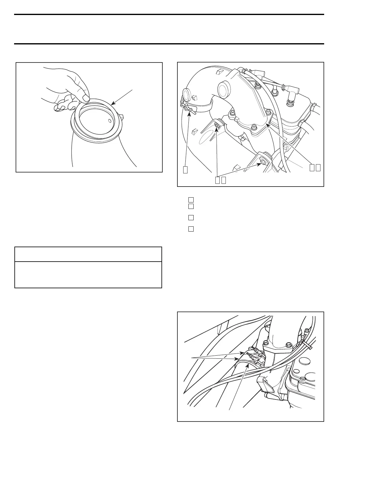
TYPICAL
1. Sealing ring
Apply a thin layer of heat resistant sealant (P/N
413 709 200) all around sealing ring.
All Models
Ensure rubber bushings
no. 19
and sleeve
no. 18
are not damaged and are properly installed into
tune pipe support(s).
Make sure that gasket
no. 20
is properly located
on exhaust manifold prior to finalizing pipe instal-
lation.
4,6,7,8,23, Clamp, Screw and Nut
Apply Loctite 242 (blue) on nut
no. 8
and screws
no. 6
and
no. 7
. Hand-tighten nut
no. 8
and
screws
no. 6
and
no. 7
and assure that tuned
pipe bushing(s)
no. 19
rests against manifold.
Refer to the following illustration for the torquing
sequence.
TYPICAL
Step : Torque screw(s) of tuned pipe cone to 12 N•m (9 lbf•ft)
Step : Torque nut and screws of tuned pipe flange in a criss-cross
sequence to 12 N•m (9 lbf•ft)
Step : Repeat the torquing sequence by retightening all fasteners
to 25 N•m (18 lbf•ft)
Step : Torque clamp to 10 N•m (88 lbf•in) (if applicable)
787 Engines
Torque nut
no. 8
and screws
no. 7
of tuned pipe
head flange to 40 N•m (30 lbf•ft).
GS, GSI, GTS and GTI Models
Install tuned pipe cone
no. 5
with collar
no. 21
and clamp
no. 22
.
Position clamp
no. 22
as illustrated. Do not tight-
en clamp yet.
1. Clamp
2. Exhaust collar
With hose removed, align cone outlet with muf-
fler inlet.
-
CAUTION
Damage to bushings and/or sleeve will
eventually cause stress to tune pipe and
may cause cracking.
F01D69A
1
F01D0IA
4
1 3
2 3
1
2
3
4
F01D41A
1
2







 To Next Page