Section 07 ELECTRICAL SYSTEM
Sub-Section 02 (IGNITION SYSTEM)
07-02-2
– start/stop function
–timer
– Digitally Encoded Security System
– ignition (GS, GSI and GTI models)
– engine rev limiter
Fuses are directly mounted onto the MPEM.
SP, GTS and HX Models
TYPICAL
GS, GSI, and GTI Models
On these models, the MPEM is also used as a
junction box, eliminating the need of an electrical
box.
All electrical components or accessories are di-
rectly linked to the MPEM.
Wire position are identified with a series of num-
ber on the MPEM. AMP plug connectors are
used.
The regulator/rectifier is also mounted on the
MPEM.
TYPICAL
787 Engine
The 787 engine has a digital Direct Current-
Capacitor Discharge Ignition (DC-CDI) system.
Compared to the magneto system, the DC-CDI
system offers a more powerful and stable ignition
at low RPM.
SPX, GSX and GTX Models
The high amperage/voltage components are lo-
cated into a rear electrical box (next to the bat-
tery).
XP Model
The high amperage/voltage components are lo-
cated into a front electrical box.
SPX and GTX Models
The other components are located in the conven-
tional electrical box.
GSX and XP Models
The other components are integrated to the Multi-
Purpose Electronic Module (MPEM).
All Models with a 787 Engine
The ignition system includes the following com-
ponents:
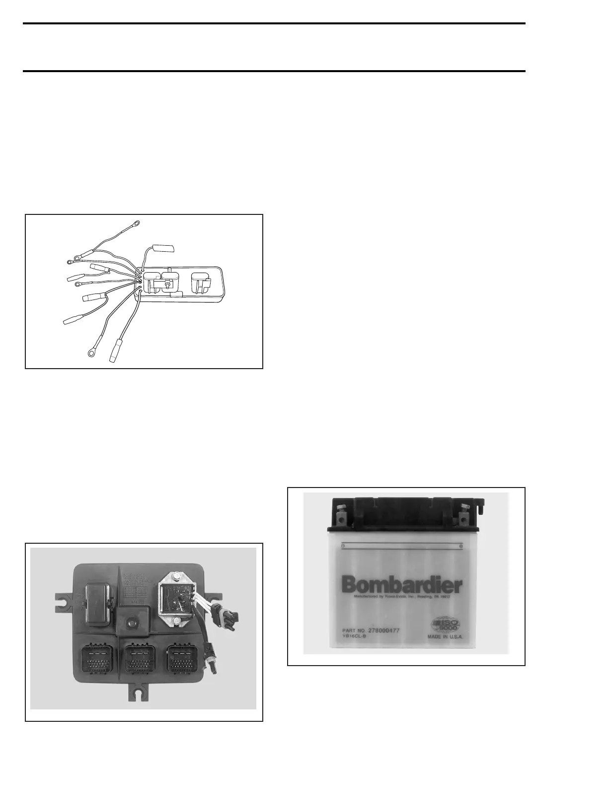
Battery
The battery is the primary power source for this
system.
F01H2OA
F00H0FA
F00H0KA
 Loading...