Section 07 ELECTRICAL SYSTEM
Sub-Section 02 (IGNITION SYSTEM)
07-02-3
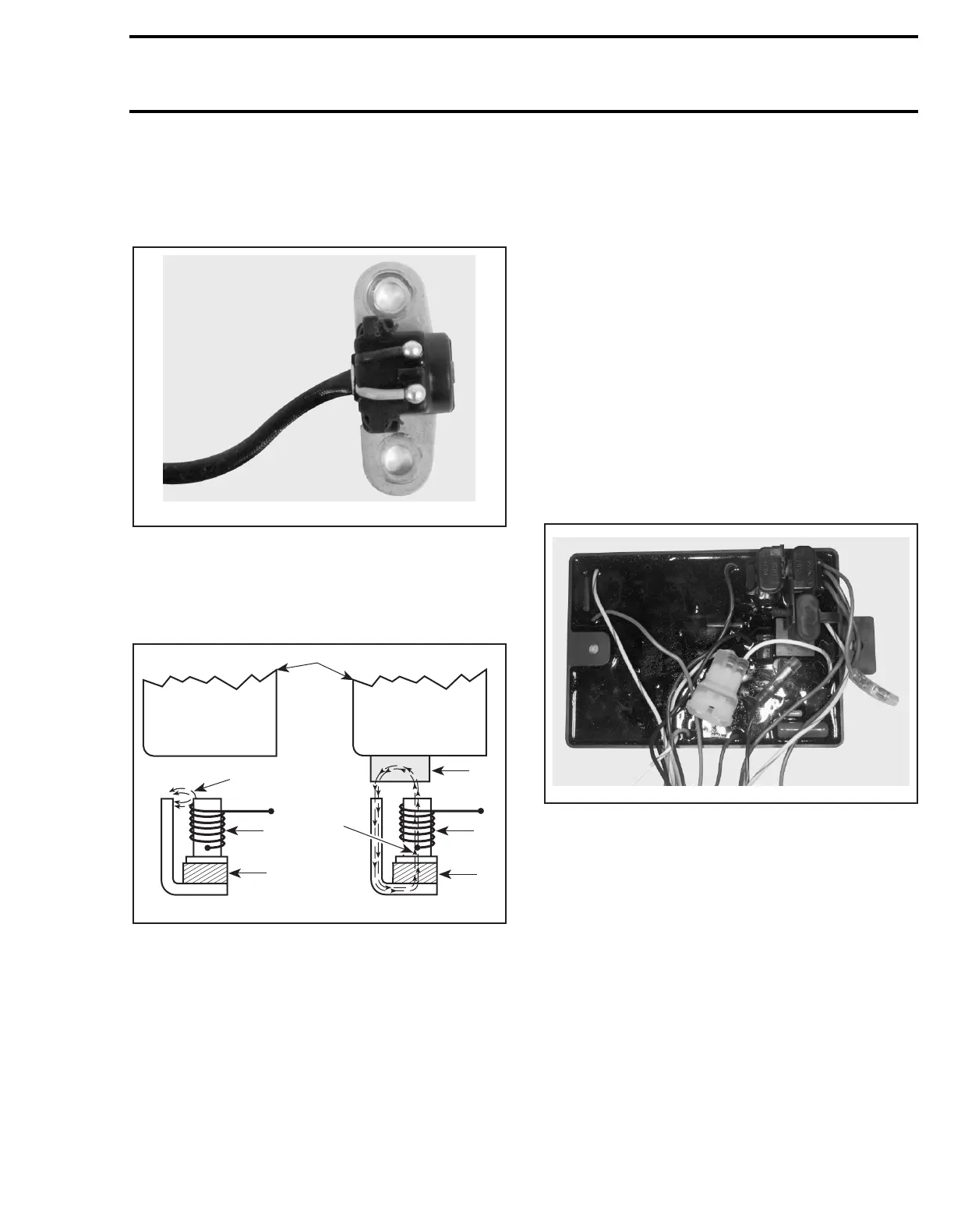
Trigger Coil
The trigger coil is mounted outside the rotor (in-
side the magneto housing of the engine) and is
not adjustable.
Its purpose is to signal the engine position to the
Multi-Purpose Electronic Module. The rotor has
two protrusions (180 degrees apart) that, when
coupled with the trigger coil, accomplish the signal-
ing.
1. Coil
2. Magnet
3. Rotor protrusion
4. Magnetic field outside of coil
5. Magnetic field crossing coil
6. Current to MPEM
Multi-Purpose Electronic Module
(MPEM)
The MPEM is directly powered by the battery. It
has a micro-processor inside of its sealed case.
The MPEM is responsible of the following electri-
cal functions:
– interpreting information
– distributing information
– start/stop function
–timer
– Digitally Encoded Security System
– ignition
– engine rev limiter
Fuses are directly mounted onto the MPEM.
SPX and GTX Models
GSX and XP Models
On these models, the MPEM is also used as a
junction box, eliminating the need of an electrical
box.
All electrical components or accessories are di-
rectly linked to the MPEM.
Wire position are identified with a series of num-
ber on the MPEM. AMP plug connectors are
used.
The regulator/rectifier is also mounted on the
MPEM.
F06H04A
N
S
N
S
A00E4JA
6
3
1
2
1
2
4
5
7
F00H0JA
 Loading...