Section 09 STEERING SYSTEM
Sub-Section 02 (SP AND SPX MODELS)
09-02-3
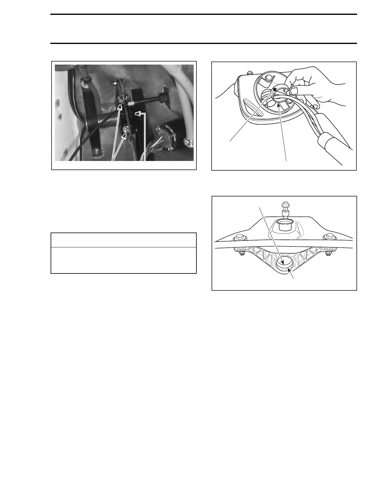
1. Bolts
2. Steering stem arm
Remove support
no. 11
and steering stem arm
no. 10
from steering stem.
NOTE:
It is not necessary to remove steering ca-
ble from steering stem arm.
Pull out handlebar assembly.
INSTALLATION
Installation is essentially the reverse of removal
procedures. However, pay particular attention to
the following.
13, Thrust Ring
Lubricate with synthetic grease thrust ring of rear
support
no. 14
and front support
no. 15
.
REAR SUPPORT
1. Apply synthetic grease
2. Thrust ring shown removed for more clarity
FRONT SUPPORT
1. Apply synthetic grease
2. Thrust ring
NOTE:
Make sure thrust rings are properly in-
stalled.
10,11, Steering Stem Arm and Support
Install support to steering stem arm.
NOTE:
Insert lock nuts
no. 17
in support. Screw
only a few threads of the bolts
no. 16
.
-
CAUTION
While performing this procedure, take pre-
cautions to avoid damaging throttle cable
and wiring harnesses.
F01K17A
2
1
1
2
F01K0HA
F01K1FA
1
2
 Loading...