Section 09 STEERING SYSTEM
Sub-Section 02 (SP AND SPX MODELS)
09-02-4
TYPICAL
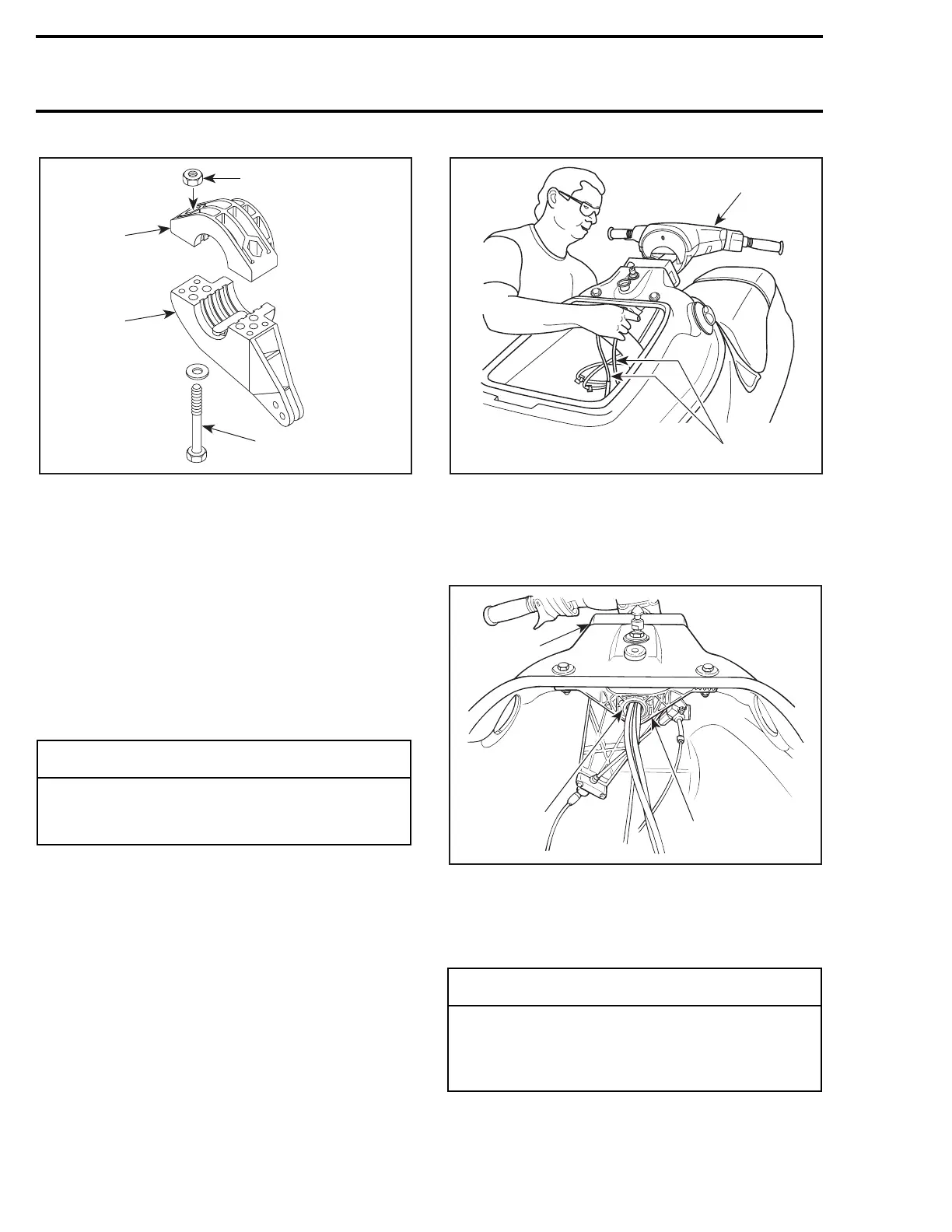
1. Support
2. Steering stem arm
3. Insert lock nuts
4. Screw only a few threads of the bolts
9,12, Steering Stem and Handlebar
Install handlebar assembly into rear support
no. 14
, taking care at the same time to insert
throttle cable and wiring harnesses.
From bilge, route throttle cable and wiring har-
nesses into support
no. 11
and steering stem arm
no. 10
, and finally in front steering support
no. 15
.
1. Install handlebar assembly
2. Route throttle cable and wiring harnesses at the same time
Push handlebar assembly until steering stem
no. 9
is well seated into steering supports
no. 14
and
no. 15
.
1. Rear support (steering collar)
2. Front support
3. Steering stem
Position steering stem arm
no. 10
and support
no. 11
onto steering stem.
-
CAUTION
While performing this procedure, take pre-
cautions to avoid damaging throttle cable
and wiring harnesses.
F01K09A
3
4
1
2
◆
WARNING
Make sure integrated flat key of steering
stem arm is properly seated in steering stem
keyway. Steering stem arm must be locked
in place before torquing the bolts.
F01K0AA
1
2
F01K1BA
1
3
2