Section 03 ENGINE
Sub-Section 05 (TOP END)
03-05-13
787 ENGINE SHOWN
1. “AUS”
Carefully cover crankcase opening as for disas-
sembly.
4,6, Piston Pin and Roller Bearing
To install roller bearing and piston pin use piston
pin puller (P/N 290 877 092), proceed as follows:
– Replacement bearings are held in place by a lo-
cating sleeve outside and 2 plastic cage halves
inside.
– Push needle bearing together with inner halves
out of the locating sleeve into the connecting
rod bore.
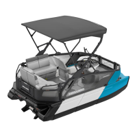
– Use any suitable 23 mm (.905 in) diameter
pusher as a tool. Make sure thrust washers are
present each side of needles.
1. Pusher
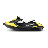
– Insert piston pin into piston until it comes flush
with inward edge of piston hub.
– Warm piston to approximately 50-60°C (122-
140°F) and install it over connecting rod.
– Insert extractor spindle into the piston pin,
screw on extracting nut.
– Rotate handle to pull piston pin carefully into
the piston.
Plastic Mounting Device Method
This is an alternate method when no service tool
is available.
Replacement roller bearings are delivered in a
convenient plastic mounting device. For installa-
tion, proceed as follows:
– Align replacement roller bearing with connect-
ing rod bore.
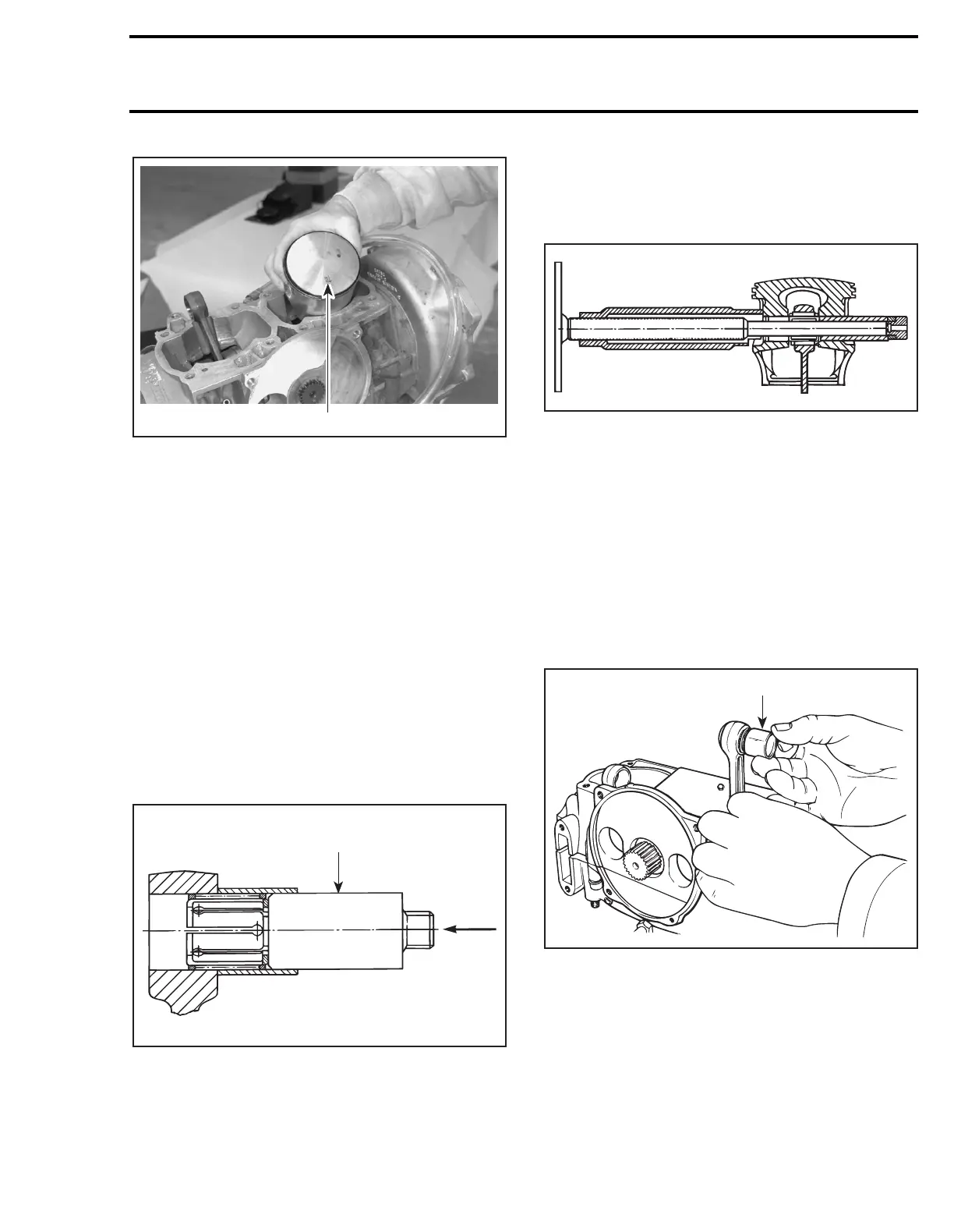
– Carefully push inner plastic sleeve into con-
necting rod bore; outer plastic ring will release
rollers.
1. Outer ring removal after inner sleeve insertion into bore
– Make sure thrust washers are present each
side of rollers.
F01D7EA
1
F01D30A
1
F01D31A
F01D0QA
1
 Loading...