Section 03 ENGINE
Sub-Section 06 (BOTTOM END)
03-06-6
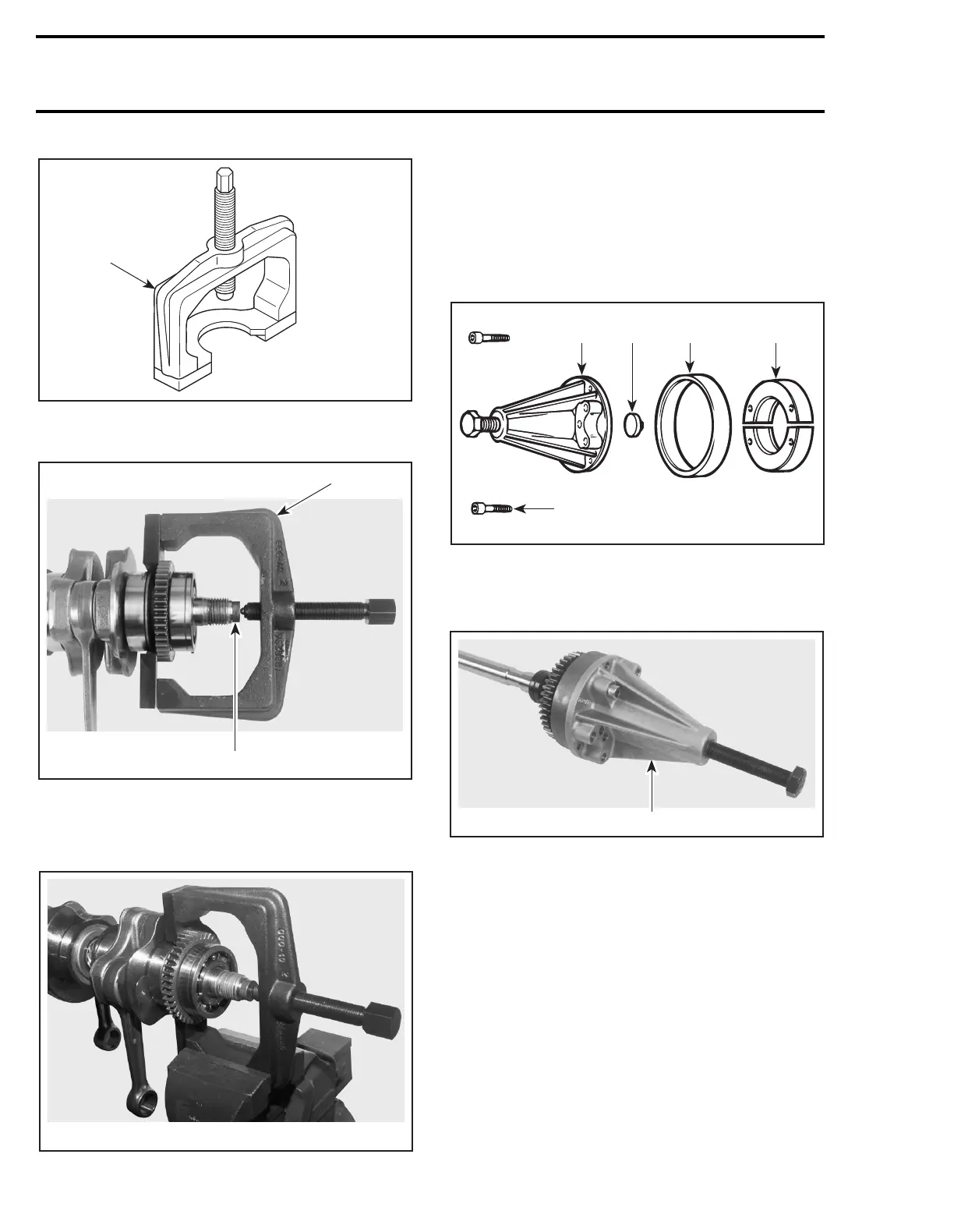
1. Puller (P/N 290 877 665)
Install the puller as per following illustration.
1. Puller
2. Protective cap
Secure puller in a vise and remove gear and bear-
ing.
NOTE:
If the inner PTO bearing needs to be re-
placed, remove the Woodruff key on the crank-
shaft.
16, Counterbalance Shaft
Bearings
no. 12
can be removed by using the fol-
lowing tools:
1. Puller (P/N 290 876 298)
2. Protective cap (P/N 290 876 557)
3. Ring (P/N 290 977 480)
4. Ring halves (P/N 290 876 330)
5. Screw M8 x 40 (P/N 290 840 681)
1. Tool installed
To remove gear
no. 18
, first trace an index mark
on the gear and counterbalance shaft.
NOTE:
There is no Woodruff key to position the
gear on the counterbalance shaft. An index mark
must be traced to ease assembly procedure.
F04B03A
1
F00D0IA
1
2
F00D0JA
F00B0CA
1 2
34
5
F00D0KA
1
 Loading...