HF Series Generators
Installation
IN-1052R0
10
14. After connecting the Power Line Cables, secure them to the Fastening
Bar using cable ties if they are routed over the Fastening Bar, or using
a suitable clamp if they are routed through the Round Cable Outlet on the
Rear Cover of the Cabinet (always apply Local Codes).
15. The Generator Cabinet is installed on the upper side of the Positioner
Control Box as follows.
CONTROL BOX
52
21
37
213
212850
65
R9.5
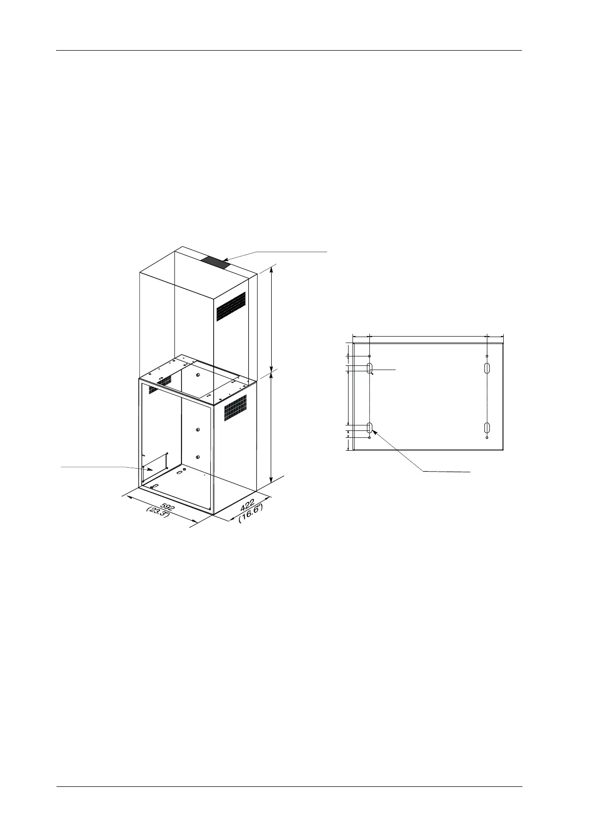
Upper Cable Entrance
COMPACT
GENERATOR
BACK COVER
Lateral Cable Entrance
Anchoring Holes
(HV Cables, Stator Cable)
690
(27.16”)
600
(23.62”)
2.55”
462
(18.18”)
65
2.55”
8.38”
These steps are also described in the Positioner Service Manual.
a. Place the Control Box on its final position of the room, keep in
mind:
G the length of the Column Harness (approx. 1.5 m) that goes
from the Column of the Positioner to the Control Box,
G the length of the High Voltage Cables (X-Ray Tube -- HV
Transformer in the Generator Cabinet),
G the Swivel Arm movements.
(Refer to Room Layout illustrations in the Positioner
Service Manual)