HF Series Generators
Installation
IN-1052R0
12
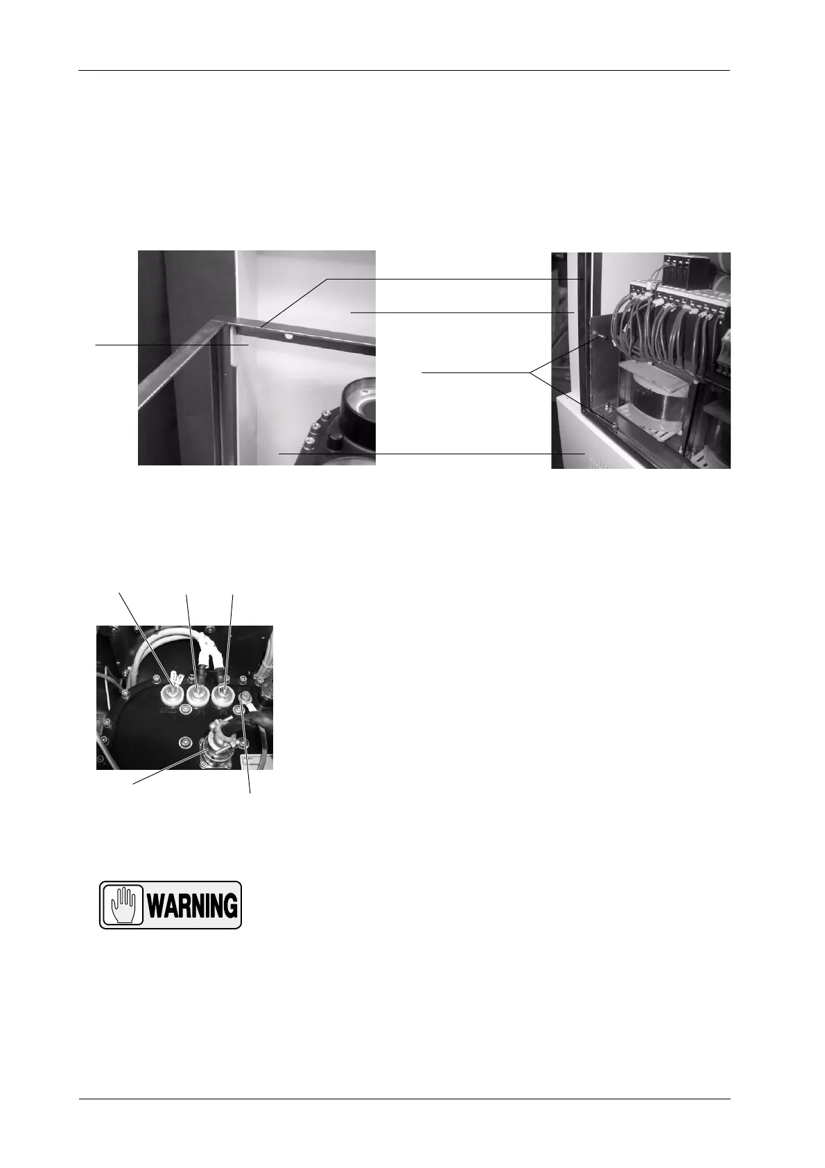
e. Hang the Generator Cabinet on the Back Cover and secure it to
the Control Box using four M6x20 screws (supplied). At least two
people are required for this operation. Fix the two screws that join
the rear side of the Cabinet to the Back Cover.
Hook
Fixing Screws
Control Box
Generator Cabinet
Back Cover
f. In some cases, due to transport safety requirements, the HV
Transformer is shipped out of the Generator Cabinet. Install the
HV Transformer inside the Cabinet (upper area) and secure it with
the respective anchors or plates, then connect the following cables
from the Power Module to the corresponding terminals on the HV
Transformer:
G P2-Shield (2 thin wires), P1 and P3. C onnect these cables to
the stud-brass terminals using two wrenches to tighten the
nuts (one to hold the base nut in place and the other to tighten
the nut over the cable) and avoiding twisting the studs. Ensure
that the c onnection is secure and properly tightened.
G Ground wire to Ground stud.
G Connector J1.
THE HV TRANSFORMER HAS TO BE SECURED WITH ITS
ANCHORS OR PLATES INSIDE THE CABINET. OTHERWISE
P1, P2 AND P3 STUDS MAY BE IN CONTACT WITH THE
CABINET FRAME AND PRODUCE A SHORT-CIRCUIT.
P2--Shield P1
P3
Ground Wire / GND Stud
J1