6- 29
Installation Conditions and Method
6
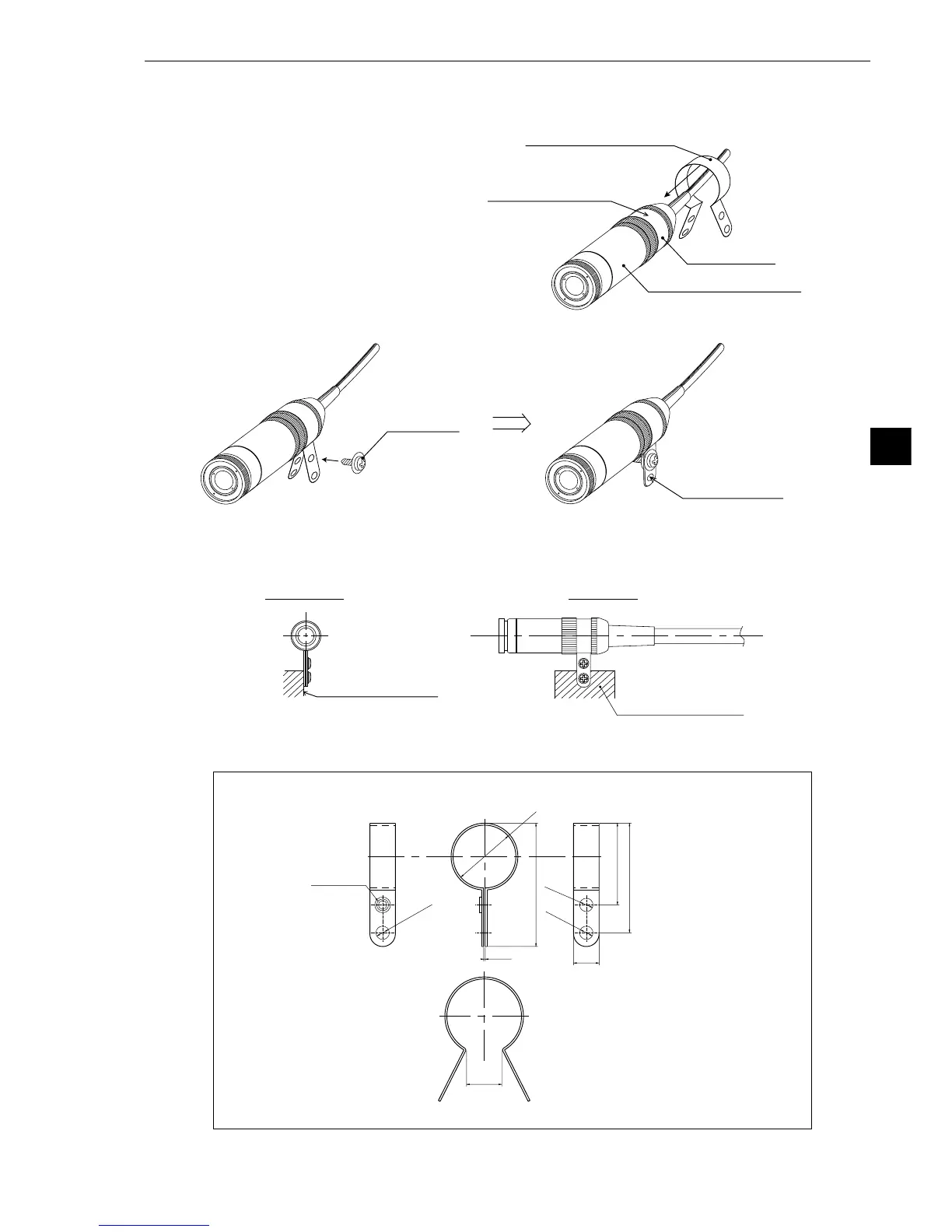
(2) Installation of the camera head
1 Put the camera head through the bracket (supplied with the IV-S30C2) from the cable side and
slide the camera head into position.
2 Secure the camera head bracket using the M3x6 screws that come with the IV-S30C2.
3 Secure the camera head assembly in place using the mounting hole (ø3.4) on the camera head
bracket.
Note: The camera head bracket supplied with the camera is for simple installations and is not
vibration-damping. To meet specific needs, the user may have to make a specialized bracket.
• External dimensions of the camera head bracket
(Shape before installation)
7 to10
6.5
φ
15.9
M3 hole
φ
3.4
φ
3.4
φ
3.4
31.4
20.8
27.9
0.4
(Unit: mm)
Front view Side view
Installation surface
Installation surface