9-21
Shared settings
9
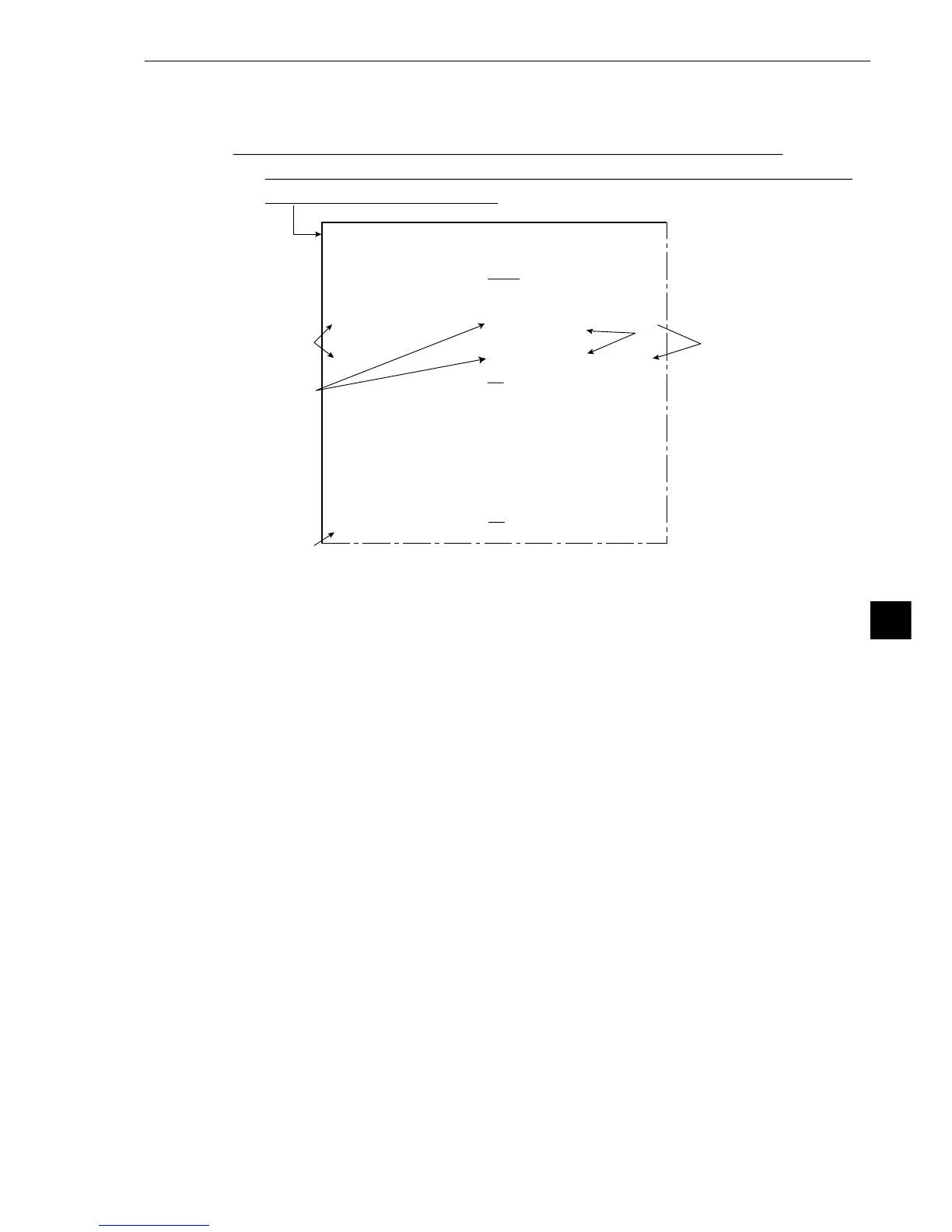
(2) Operation setting details
Setting takes place at camera (1/2) in items 5 and 6 on the [OBJECT TYPE COND] (conditions
of object type) menu.
[Setting procedure]
1. Select item 5 POS. ADJ. CAMERA 1 for camera 1, or item 7 POS. ADJ. CAMERA 2 for
camera 2, using the up and down keys.
2. Move the cursor to [NO ADJ.] (no adjustment) using the left and right keys. Then select
either X and Y correction, angular correction (standard) or angular correction (high
precision), using the up and down keys.
3. Move the cursor to [REG. 0] (register 0) using the left and right keys and then select [0 to 7]
using the up and down keys.
- Registration No. 0 to 7 correspond to register No.0 to 7 [MEASURING COND]
(measurement condition) menu in positional deviation measurement.
4. In the case of an X and Y correction, move the cursor to 1PNTSXY (first X and Y point)
using the left and right keys and then select XY or X or Y using the up and down keys.
- In the case of angular correction, it is unnecessary to perform step 4.
5. Press the SET key. Move the cursor to item u UPPER MENU and press the SET key.
This completes the settings for positional correction.
On the MAIN OPS MENU, move the cursor to SET-SCRN item, and press the SET key.
- On the [SYSTEM SETUP] menu, move the cursor to 2 OBJECT TYPE COND (conditions of
object type) and press the SET key.
1
4
3
5
2
[OBJECT TYPE COND]
1OBJECT TYPE NO.
00(0~15)
2EDIT
COPY(←OBJTYPE00) INITIALIZE
3TITLE REGISTRATION
(TO NEXT SUB-MENU)
4MEAS.0, CAMERA1
NO (TO NEXT SUB-MENU)
5POS. ADJ.CAMERA1 NO ADJ. [
REG. 0-1PNTSXY]
6MEAS.0, CAMERA2
NO (TO NEXT SUB-MENU)
7POS. ADJ.CAMERA2 NO ADJ. [
REG. 0-1PNTSXY]
8SELECT CAMERA IMG
NO CAM1 CAM1 CAM1&2
0MEASUREMENT 1
NO (TO NEXT SUB-MENU)
qMEASUREMENT 2
NO (TO NEXT SUB-MENU)
wMEASUREMENT 3
NO (TO NEXT SUB-MENU)
eFINAL CALC RESULT
(TO NEXT SUB-MENU)
rFINAL OUTPUT COND
(TO NEXT SUB-MENU)
tSYSTEM-IN/OUT
(TO NEXT SUB-MENU)
yHALT MEAS ON NG
NO YES
uUPPE
R MENU