Continued on the following page
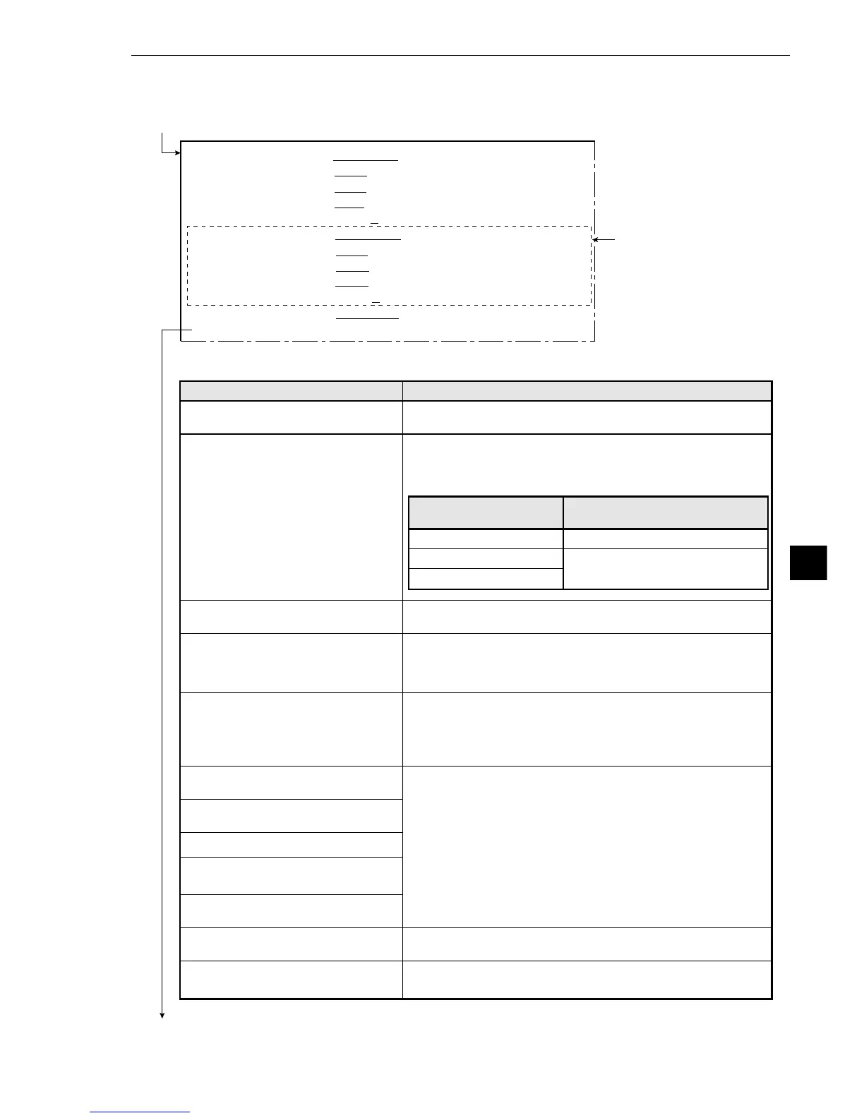
· You can switch between displaying all of the headings together and displaying each one separately
by using the ESC key.
1MEAS WINDOW(MDL0) RECTANGLE
X-LINE Y-LINE
2REF IMAGE(MODEL0) MOVE UP.L(224,208) LO.R(287,271) REG. DISP
3SEARCH AREA(MDL0) MOVE UP.L(
216,200)
LO.R(
295,279)
4DTECT COORD(MDL0)
CNTR FREE(256,240)
5CONTR. PIXEL(MDL0)
1 2 3
6MEAS WINDOW(MDL1) RECTANGLE
X-LINE Y-LINE
7REF IMAGE(MODEL1) MOVE UP.L(224,208) LO.R(287,271) REG. DISP
8SEARCH AREA(MDL1) MOVE UP.L(
224,512)
LO.R(
287,512)
9DTECT COORD(MDL1)
CNTR FREE(256,240)
0CONTR. PIXEL(MDL1)
1 2 3
qDETECT ACCURANCY
STANDARD HI-PRC
wUPPER MENU
These items in the dotted
line are only displayed
when 2-point search is
selected.
Continued from the previous page
Specify a 1P-SCH (1-point search), a 2P-SCH (2-point search), or a 1P-SCH+1P-EDGE (1-point search + 1-
point edge) in item 2 SELECT MODE. Then select item 3 GRAY-SCALE COND (gray scale search
Menu
1MEAS WINDOW(MDL0)
(measurement window)
2REF IMAGE(MODEL0)
(reference images)
3SEARCH AREA(MDL0)
(search area)
4DTECT COORD(MDL0)
(detection coordinates)
5CONTR. PIXEL(MDL0)
(pixel contraction)
6MEAS WINDOW(MDL1)
(measurement window)
7REF IMAGE(MODEL1)
(reference images)
8SEARCH AREA(MDL1)
9DTECT COORD(MDL1)
(detection coordinates)
0CONTR. PIXEL(MDL1)
(pixel contraction)
qDETECT ACCURACY
(accuracy of detection)
wUPPER MENU
Setting details
Select the measurement window shape for model 0.
Record a reference image for model 0
· The upper left or lower right area of the screen specified
above will change according the setting in item 1 MEAS
WINDOW(MDL0).
Set the search area for model 0.
Set the position of the cursor inside the measurement
window for model 0.
· If FREE is selected, then the position of the cursor is
optional.
Select number of pixel contractions for model 0.
-See page 9·6 gray scale processing using shared settings.
· When either X-LINE (horizontal line) or Y-LINE (vertical
line) are selected in item 1 MEAS WINDOW(MDL0), you
can select only 1 or 2 in item 5.
Set these items for model 1 just the same way as item 1 to
5 above.
Set the level of detection precision for models 0 and 1.
-See page 9·6 gray scale processing in shared settings.
This will return you to the menu [MEASURING COND]
(measurement conditions) menu.
RECTANGLE (rectangle)
X-LINE (horizontal line)
Y-LINE (vertical line)
The display in the upper left and
lower right areas of the screen.
Upper left, lower right.
Starting point, end point
The setting at
item 1