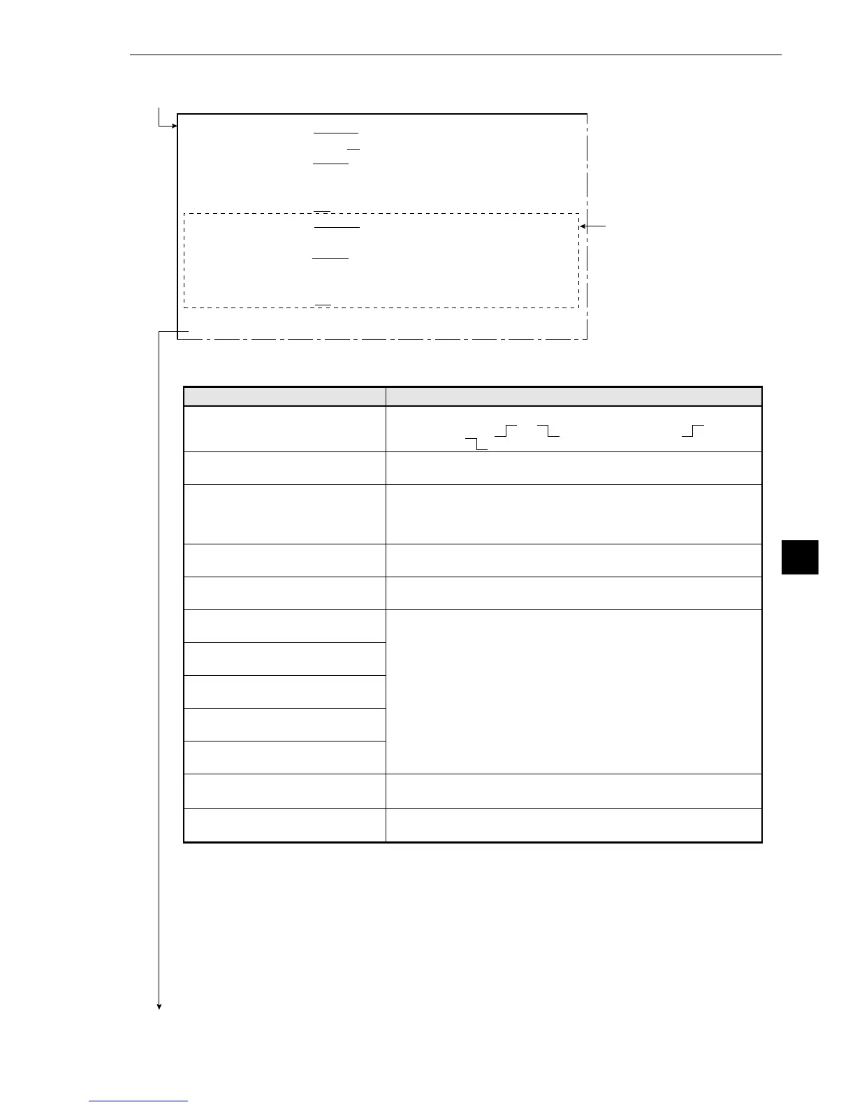
These items in the dotted
line are only displayed
when 2-point edge is
selected.
· You can switch between displaying all of the headings together and displaying each one
separately by using the ESC key.
· For more information about the settings for edge detection see page 9·11, Edge detection, in
shared settings.
1DETECT MODE(MDL0) CHANGE DRK→BRT BRT→DRK CNTR(BRT DRK)
2DETECT DIR.(MDL0) HORI (→ ←) VERT (↓ ↑)
3DETECT AREA(MDL0)
MOVE UP.L(224,208) LO.R(287,271)
4THRESHOLD(MODEL0)GRYS.LO050(0~255) EDGE.W (1~8)
FLAT.W04(1~16)
5PRC.PROJECT(MDL0)
NO YES
6DETECT MODE(MDL1) CHANGE DRK→BRT BRT→DRK CNTR(BRT DRK)
7DETECT DIR.(MDL1)
HORI (→ ←) VERT (↓ ↑)
8DETECT AREA(MDL1)
MOVE UP.L(224,208) LO.R(287,271)
9THRESHOLD(MODEL1)GRYS.000(0~255) EDGE.W (1~8)
FLAT.W04(1~16)
0PRC. PROJECT(MDL1)
NO YES
qREG REF COORD SET KEY ( , ) ( , )
wUPPER MENU
Continued on the following page
Continued from the previous page, or from page 9·36: When you specified a 1P-EDGE (1-point edge),
2P-EDGE (2-point edge) or 1P-SCH + 1P-EDGE (1-point search + 1-point edge)
Menu
1DETECT MODE (MDL0)
(detection mode)
2DETECT DIR. (MDL0)
(detection direction)
3DETECT AREA (MDL0)
(area of detection)
4THRESHOLD (MODEL0)
(threshold values)
5PRC. PROJECT (MDL0)
(artifact processing)
6DETECT MODE (MDL1)
(detection mode)
7DETECT DIR. (MDL1)
(detection direction)
8DETECT AREA (MDL1)
(area of detection)
9THRESHOLD (MODEL1)
(threshold values)
0PRC. PROJECT (MDL1)
(artifact processing)
qREG REF COORD (register
reference coodinates)
wUPPER MENU
Setting details
Select the detection mode for model 0.
(Point of change: or , From dark to light: From
light to dark: Centering (light or dark center))
Select the direction in which detection will take place for
model 0.
Set up a dotted line rectangular perimeter around the search
area for model 0.
· In order to increase the speed of the searches, make the
length of Y as small as possible.
Set the width of the edge (1 to 8) and the flat (1 to 16), as well
as the difference in the light level (0 to 255).
Select whether to employ artifact processing in model 0 or not.
-See page 9·12, artifact processing.
Set these items for model 1 just the same way as item 1 to
5 above.
Register a coordinate, which is used as the reference point for
edge detection.
This will return you to the [MEASURING COND]
(measurement condition) menu.